Sound-Transmitting Member

a technology of sound-transmitting member and sound-transmitting device, which is applied in the direction of waterborne vessel navigational aids, instruments, transportation and packaging, etc., can solve the problems of large system performance impact, inability to achieve a practically sufficient high frequency bandwidth, and difficulty in using in a high frequency band of 20 khz or greater, so as to improve sound-transmitting characteristics, reduce pressure, and reduce reflection

Inactive Publication Date: 2016-10-13
THE YOKOHAMA RUBBER CO LTD
View PDF2 Cites 4 Cited by
  • Summary
  • Abstract
  • Description
  • Claims
  • Application Information

AI Technical Summary

Benefits of technology

This technology provides a way to reduce noise in devices that use sound-transmitting members. It does this by adding multiple layers that absorb or suppress the oscillation, which can cause noise. This helps to improve the performance of devices that use sound-transmitting members. Additionally, a protective layer can be added to make the sound-transmitting member stronger and less affected by pressure from the surrounding fluid and marine organisms.

Problems solved by technology

Such conventional sound-transmitting members are essentially single-layer structures with excellent sound-transmitting characteristics in the low frequency region of a few kHz or less, but are difficult to use in a high frequency band of 20 kHz or greater.
As a result, the frequency f indicated in the above-described formula (6) shifts due to the temperature, resulting in a large impact on system performance.
Accordingly, the conventional technology is capable of expanding the transmission bandwidth in the sound-transmitting member, but cannot attain a practically sufficient bandwidth in the high frequency region.

Method used


Image

  • Sound-Transmitting Member
  • Sound-Transmitting Member
  • Sound-Transmitting Member

Examples


first embodiment

[0045]FIG. 1 is an explanatory drawing illustrating a configuration of a marine sonar device 20 equipped with a sound-transmitting member. The sound-transmitting member according to the present technology is used in order to form a sound-transmitting region α in the sonar device 20, for example.

[0046]The sonar device 20 is disposed at a leading end of a sonar device support platform (not illustrated) provided in the body of a ship.

[0047]The sonar device 20 includes a transducer 24 and an acoustic window 26.

[0048]The transducer 24 is mounted on a frame 28 made of fiber reinforced plastics (FRP) supported on the inside of the acoustic window 26, and is disposed towards the front of the ship.

[0049]The acoustic window 26 is intended for protecting the transducer 24 and is provided so as to cover the transducer 24, with water filling the inside of the acoustic window 26.

[0050]The acoustic window 26 has a cylindrical portion 26A, and a curved surface portion 26B that is formed in a curved...

second embodiment

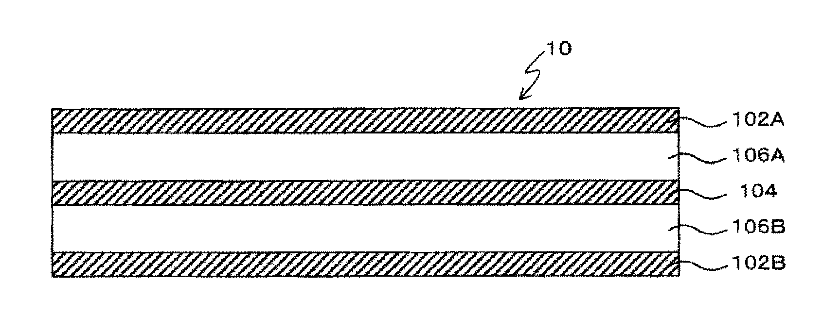
[0094]In the first embodiment, one intermediate layer and two core layers are disposed between the two skin layers, the intermediate layer and the core layer being alternately stacked (N=1).

[0095]In the second embodiment, the number of intermediate layers and core layers is increased, and N intermediate layers and N+1 core layers are disposed between the two skin layers, the intermediate layer and the core layer being alternately stacked (N≧2).

[0096]FIGS. 8A and 8B are explanatory drawings illustrating configurations of sound-transmitting members 30 and 40 according to the second embodiment.

[0097]The sound-transmitting member 30 illustrated in FIG. 8A includes two skin layers 302A and 302B, two intermediate layers 304A and 304B, and three core layers 306A, 306B, and 306C, in which the intermediate layer and the core layer are alternately stacked between the skin layers (N=2). More specifically, the layers are stacked in the following order from the top of FIG. 8A: the skin layer 302...


PUM

PropertyMeasurementUnit
thicknessesaaaaaaaaaa
elastic modulusaaaaaaaaaa
frequencyaaaaaaaaaa

Abstract

To obtain a sound-transmitting member having a wide sound-transmitting band in a high frequency region. A planar sound-transmitting member having sound-transmitting properties includes two skin layers, N+1 core layers, and N intermediate layers (N=1), in which the core layer and the intermediate layer are alternately stacked between the skin layers. The skin layers and the intermediate layer are formed of carbon fiber reinforced plastics (CFRP), which is a material having a higher elastic modulus than the core layers formed of rubber.

Description

TECHNICAL FIELD[0001]The present technology relates to a sound-transmitting member having sound-transmitting properties.BACKGROUND ART[0002]Conventionally, sound-transmitting members having sound-transmitting properties have been used for a sound-transmitting region of a device such as marine sonar. A member formed of steel is a typical example of a conventional sound-transmitting member, but rubber sound-transmitting members such as rubber domes or rubber windows are known as an improved structure for the conventional sound-transmitting members. Such conventional sound-transmitting members are essentially single-layer structures with excellent sound-transmitting characteristics in the low frequency region of a few kHz or less, but are difficult to use in a high frequency band of 20 kHz or greater.[0003]In U.S. Pat. No. 4,997,705B, a sound-transmitting member that employs a sandwich structure in which both surfaces of a core layer are covered by skin layers is disclosed.[0004]FIG. 1...

Claims


Application Information

Patent Timeline
Patent Type & Authority Applications(United States)
IPC IPC(8): G01S7/521B32B25/08B32B7/02B32B7/022
CPCG01S7/521B32B7/02B32B25/08B32B2262/106B63B2201/18B32B2307/51B32B2605/12H04R1/026H04R1/028B32B2307/10B63B49/00H04R1/44B32B27/20B32B2250/05B32B7/022
Inventor TADOKORO, MASATOTANAKA, YUSUKE
Owner THE YOKOHAMA RUBBER CO LTD
Why Eureka
Try Eureka