
Method and apparatus for processing pixels in video encoding and decoding

a video encoding and decoding technology, applied in the field of video encoding and decoding, can solve the problems of increasing the processing complexity of a codec, affecting the performance of encoding, and the deblocking filter may not process the pixels of the right boundary and the bottom boundary of the current encoding processing block,

Inactive Publication Date: 2016-09-29
SAMSUNG ELECTRONICS CO LTD
View PDF1 Cites 3 Cited by
  • Summary
  • Abstract
  • Description
  • Claims
  • Application Information

AI Technical Summary

Benefits of technology

This patent provides a new video encoding and decoding method that divides an image into smaller processing regions to improve coding performance. By using a new offset method, the method and apparatus can save bit rate and improve encoding performance. Additionally, the method allows for more flexibility in determining the sample offset processing region, which can reduce execution costs and improve prediction accuracy. This patent also provides a new sample offset method that allows for more efficient information transmission and savage of bit rate.

Problems solved by technology

However, since the reconstruction of the bottom adjacent encoding processing block and the right adjacent encoding processing block of the current encoding processing block is not yet completed, the deblocking filter may not process the pixels of the right boundary and the pixels of the bottom boundary of the current encoding processing block.
This increases the processing complexity of a codec.
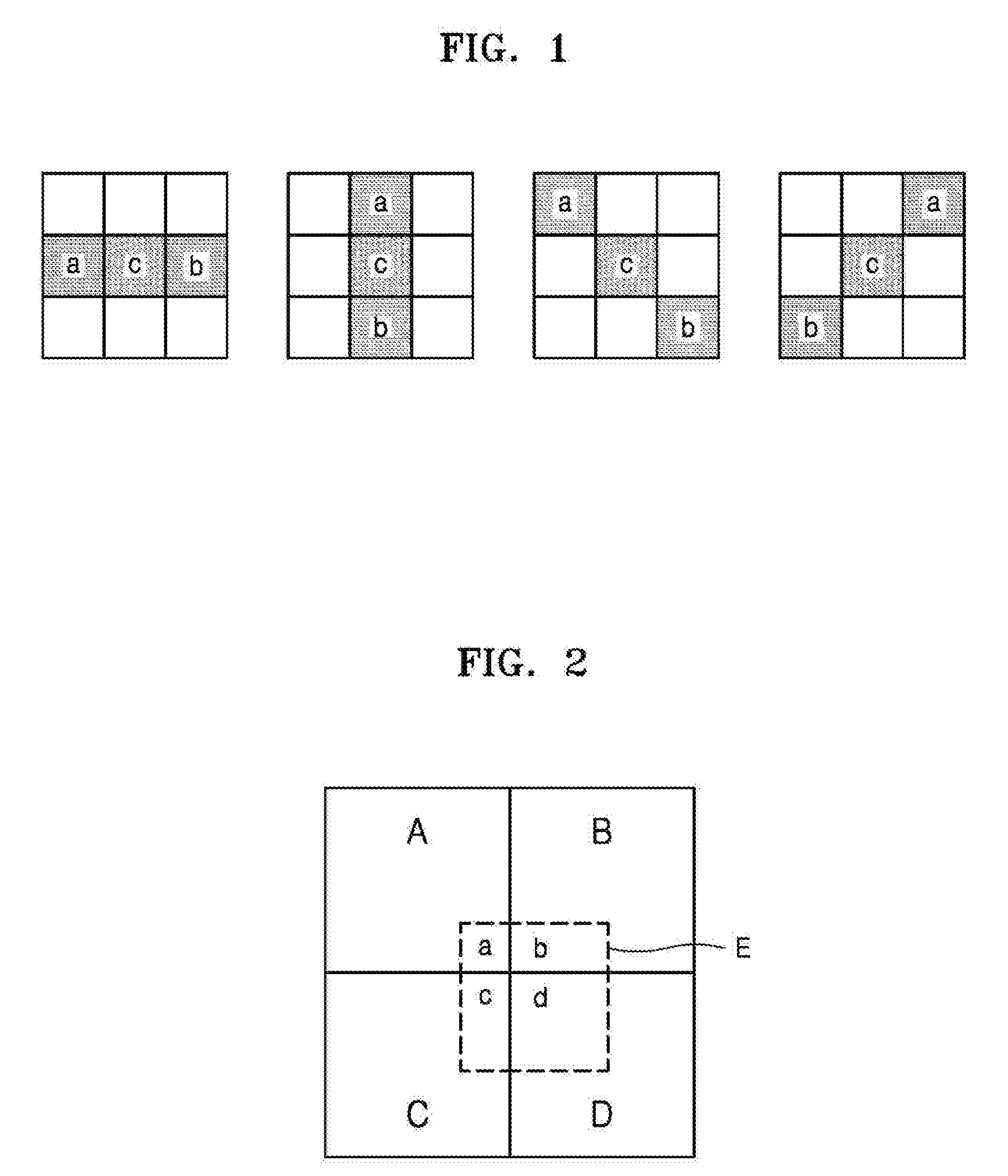
Since the values of the pixels on the bottom boundary and the pixels on the right boundary of the block D are not yet deblocking-filtered, the encoder may not clearly predict the optimal sample adaptive offset parameters for processing these pixels causing the encoding performance degradation.
In the sample adaptive offset processing of the HEVC, the characteristics of an input image are not considered, and the processing is not flexible because the largest coding unit is always determined as the sample adaptive offset processing unit.

Method used


Image

  • Method and apparatus for processing pixels in video encoding and decoding
  • Method and apparatus for processing pixels in video encoding and decoding
  • Method and apparatus for processing pixels in video encoding and decoding

Examples


embodiment 1

[0079]According to an embodiment of the present disclosure, the largest coding unit is determined as the coding processing unit and the spatial position movement operation is performed.

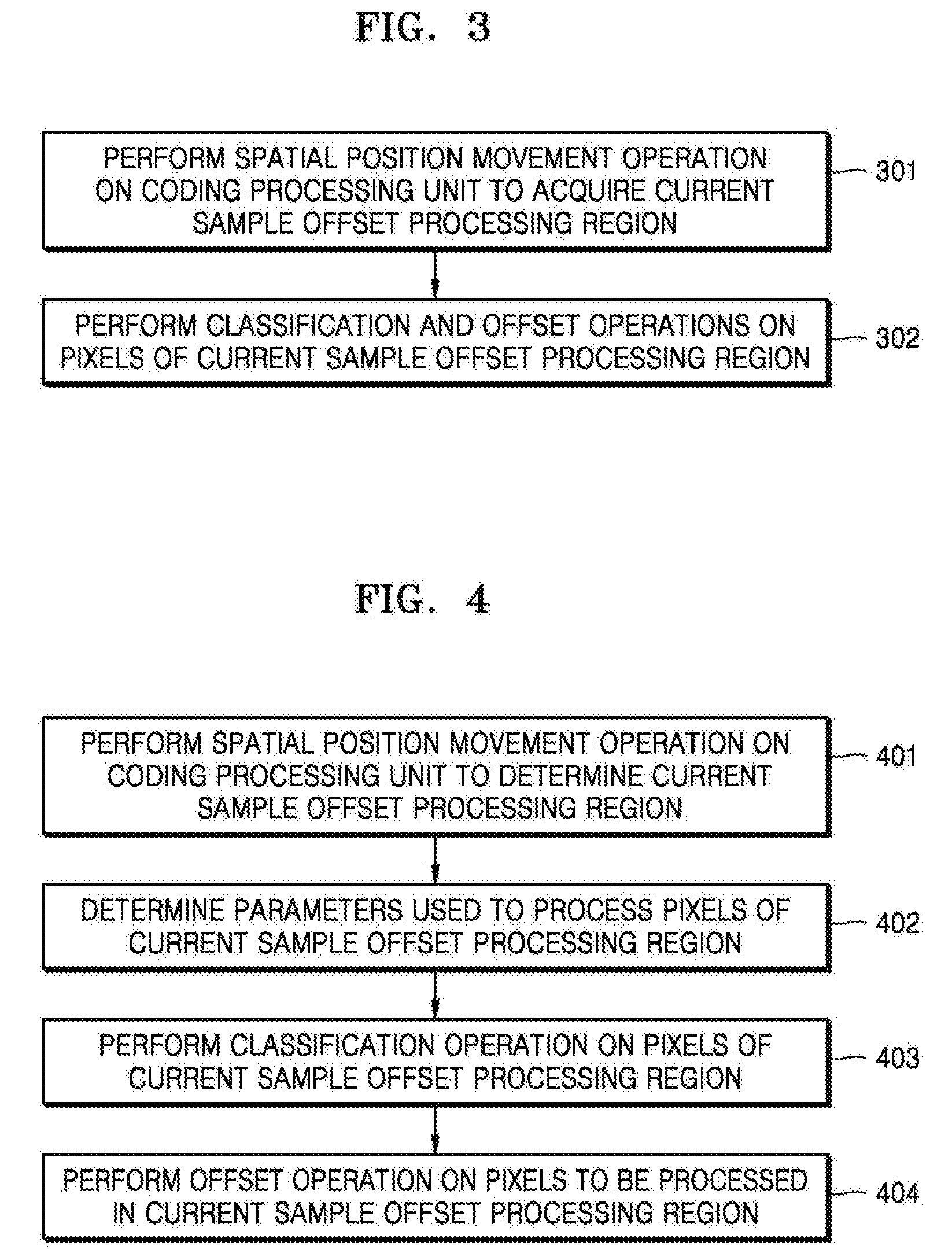
[0080]FIG. 4 is a flow diagram illustrating pixel processing methods according to Embodiments 1 to 4 of the present disclosure. The flow may include the following process.

[0081]In operation 401, the spatial movement operation may be performed on the coding processing unit to determine the current sample offset processing region.

[0082]In an embodiment of the present disclosure, the current sample offset processing region may be acquired by moving the current largest coding unit to the top left side by the distance of N pixels. Herein, “being moved to the top left side by the distance of N pixels” may represent “being moved to the left side by the distance of N pixels and then to the top side by the distance of N pixels”, and “N” may be specified when necessary. For example, “N” may be “4”. Specifically...

embodiment 2

[0089]According to an embodiment of the present disclosure, a group of several largest coding units may be determined as the coding processing unit, and then the spatial position movement operation may be performed.

[0090]Referring to FIG. 4, the flow of a pixel processing method according to an embodiment of the present disclosure may include the following process.

[0091]In operation 401, the spatial position movement operation may be performed on the coding processing unit to determine the current sample offset processing region.

[0092]In an embodiment of the present disclosure, the current sample offset processing region may be acquired by moving a group of several adjacent largest coding units by the distance of eight pixels. FIG. 7 is a schematic diagram illustrating sample offset processing regions of the present disclosure. As illustrated in FIG. 7, the solid-line blocks may be the largest coding units and the dotted-line blocks may be the sample offset processing regions. Six l...

embodiment 3

[0101]According to an embodiment of the present disclosure, the coding unit may be determined as the coding processing unit and the spatial position movement operation may be performed.

[0102]As illustrated in FIG. 4, the flow of the pixel processing method in the present embodiment may include the following process.

[0103]In an embodiment of the present disclosure, the current sample offset processing region may be acquired by moving the current coding unit to the top left side by the distance of two pixels, for example, by moving the current coding unit to the left side by the distance of two pixels and then to the top side by the distance of two pixels. FIG. 8 is a schematic diagram illustrating sample offset processing regions in an embodiment of the present disclosure. As illustrated in FIG. 8, the solid-line blocks may be the coding units and the dotted-line blocks may be the sample offset processing regions. As illustrated in the block E0, the current sample offset processing r...


PUM


Abstract

The present disclosure provides a method of processing pixels in video encoding and decoding, the method including determining a current sample offset processing region and performing classification and offset operations on pixels of the current sample offset processing region, wherein the determining of the current sample offset processing region includes performing a spatial position movement operation on a predetermined coding processing unit and determining a region after the spatial position movement operation as the current sample offset processing region. By using the present disclosure, the sample offset processing regions may be flexibly acquired and the encoding performance may be improved.

Description

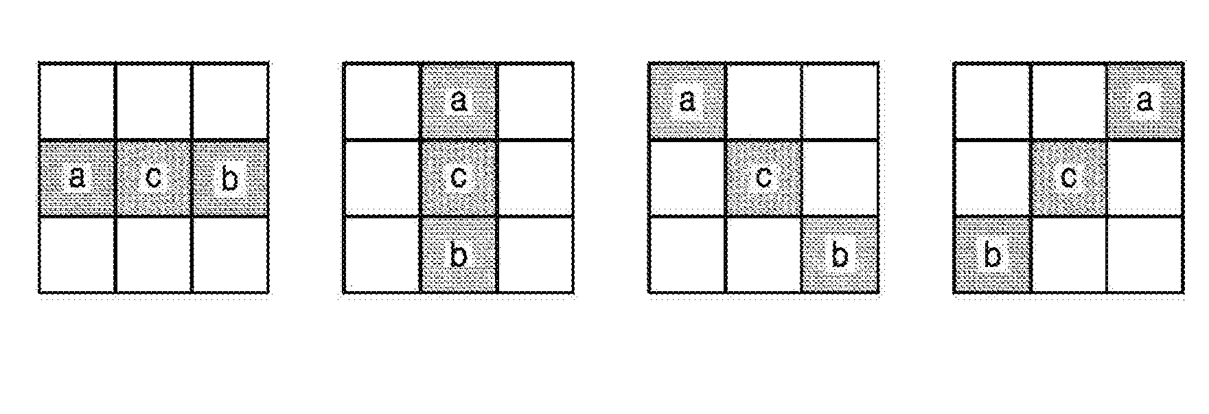
TECHNICAL FIELD[0001]The present disclosure relates to video encoding and decoding, and more particularly, to methods and apparatuses for processing pixels in video encoding and decoding.BACKGROUND ART[0002]High-efficiency video coding (HEVC) is an international video coding standard that uses a sample adaptive offset technology to reduce distortion between original pixels and reconstructed pixels. In the technology, pixels of a region are classified by category and an offset value is added to the pixel. A process of classifying the pixels in the region and adding the offset value to the pixel needs to be performed in both an encoder and a decoder. In addition, the encoder needs to transmit information about offset values added to pixels of different categories in a bitstream and about a classification method used, but does not need to transmit information about pixels included in each category. After acquiring a current classification method, in order to obtain the same classificat...

Claims


Application Information

Patent Timeline
IPC IPC(8): H04N19/182H04N19/174H04N19/117
CPCH04N19/182H04N19/174H04N19/117H04N19/172H04N19/14H04N19/82H04N19/86Y02E60/36
Inventor CHEN, JIEALSHINA, ELENA
Owner SAMSUNG ELECTRONICS CO LTD
Learn More