
Drainless reverse osmosis water purification system

a reverse osmosis and water purification system technology, applied in the direction of multi-stage water/sewage treatment, membranes, separation processes, etc., can solve the problems of chlorine-based contaminants, particulate contaminants retention, etc., to prolong the service life of the ro membrane, quick and easy slide-out removal, and eliminate water waste

Active Publication Date: 2016-09-29
DS SERVICES OF AMERICA INC
View PDF12 Cites 2 Cited by
  • Summary
  • Abstract
  • Description
  • Claims
  • Application Information

AI Technical Summary

Benefits of technology

This patent is about an improved drainless reverse osmosis water purification system that recycling retentate or brine in a way that reduces water waste. The system includes a catalyst pre-filter for removing contaminants from tap water before reaching the reverse osmosis membrane, which extends the life of the membrane. The membrane is part of a multi-cartridge unit that can be easily replaced when needed. The system also includes a source of filtered, relatively purified air. During pure water production, the system recycling the brine outflow to the tap water supply, which helps to reduce water waste. The produced purified water can be used for on-demand dispensing or stored in a reservoir for later use. The multi-cartridge unit is designed for easy installation and replacement. Overall, this system helps to produce purified water with reduced waste and improved quality.

Problems solved by technology

During normal operation of the RO system to produce relatively purified water, a relatively slow tap water flow proceeds upwardly through the catalyst particulate, at a rate and pressure insufficient to disturb the catalyst bed, resulting in catalyzation of chlorine-based contaminants such as chlorine and chloramines to other forms not harmful to the RO membrane, as well as retention of particulate contaminants.

Method used


Image

  • Drainless reverse osmosis water purification system
  • Drainless reverse osmosis water purification system
  • Drainless reverse osmosis water purification system

Examples


Embodiment Construction

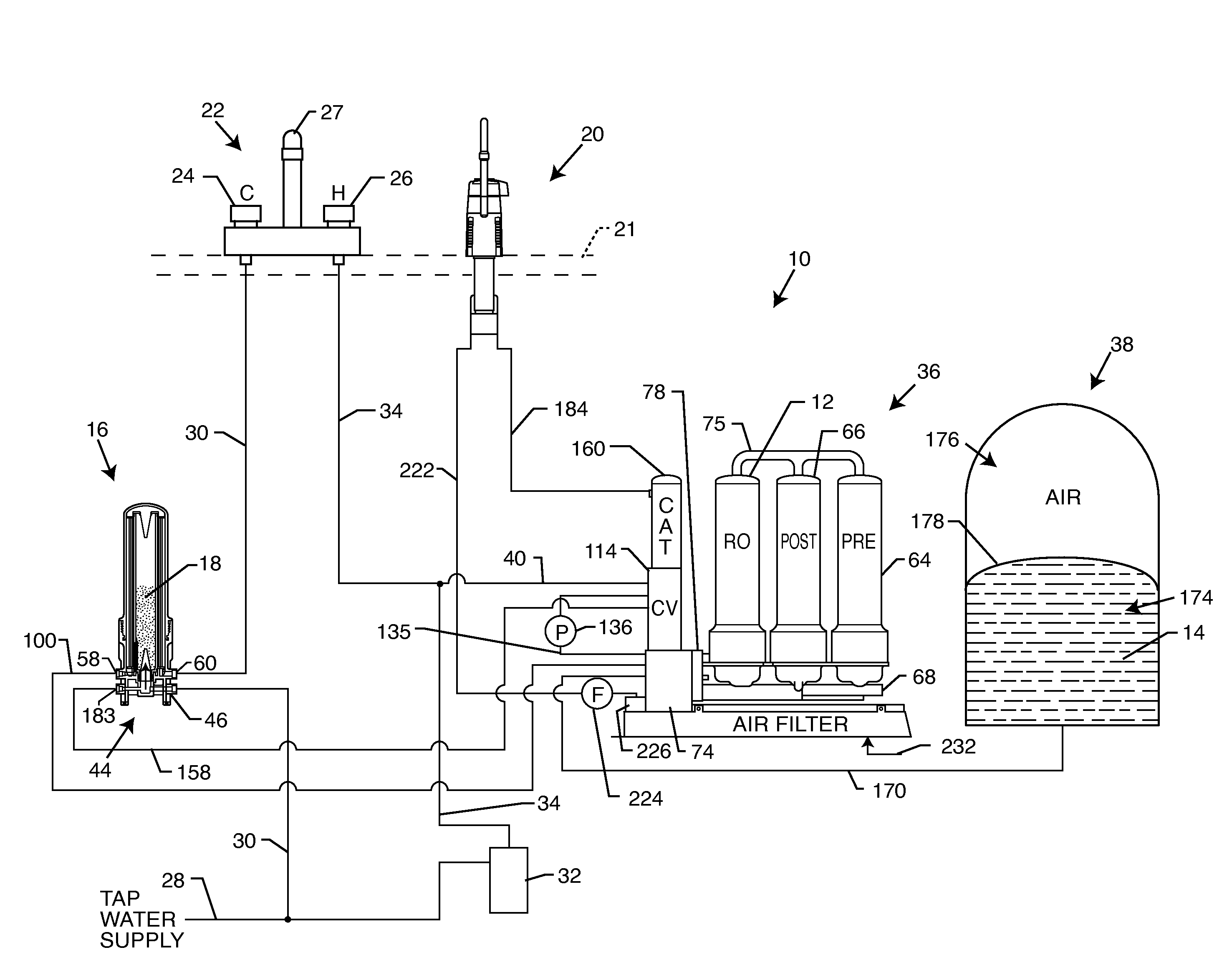
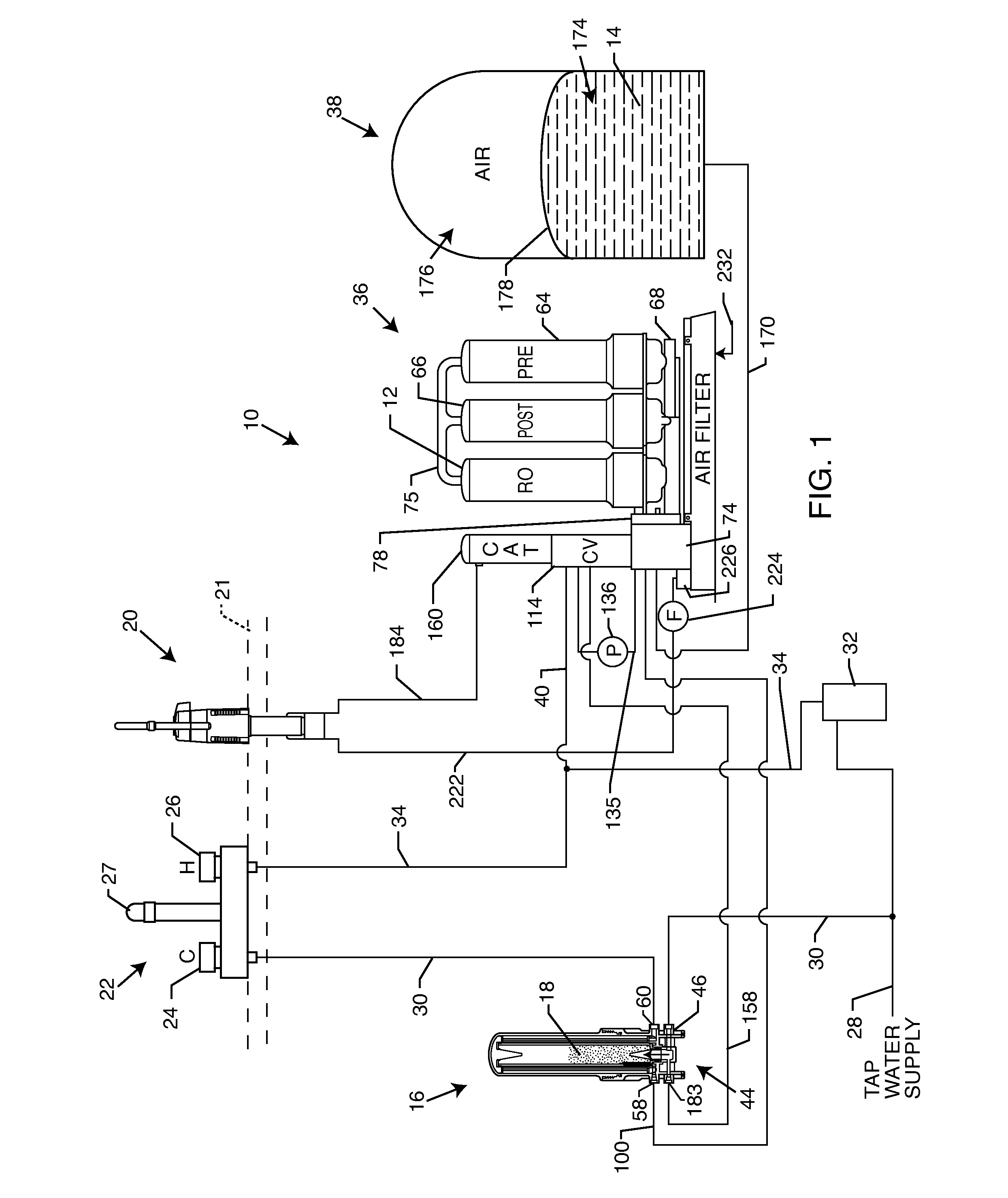
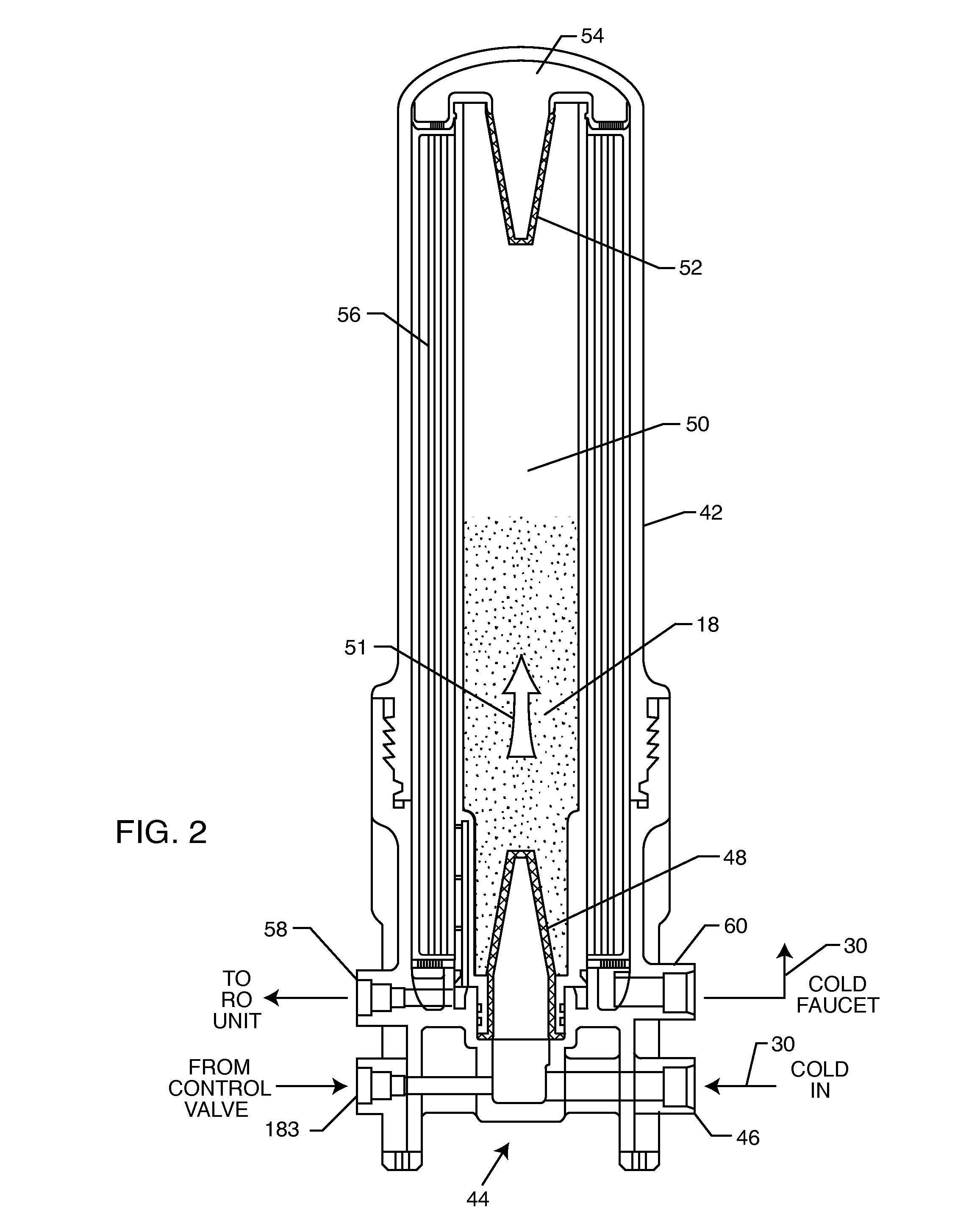
[0042]As shown in the exemplary drawings, an improved reverse osmosis (RO) water purification system referred to generally in FIG. 1 by the reference numeral 10 includes a reverse osmosis (RO) cartridge 12 having a reverse osmosis (RO) membrane therein for separating a tap water inflow into relatively purified water 14 available for on-demand dispensing, and a so-called retentate or brine flow having contaminants and impurities substantially concentrated therein. In accordance with the invention, during pure water production, the brine flow is recycled to a hot water side or hot water circuit of a domestic water supply system to avoid water waste. In addition, tap water inflow to the RO cartridge is pretreated by flow through a catalyst pre-filter 16 to catalyze chemical contaminants which would otherwise be harmful to the RO membrane, thereby significantly increasing the service life of the RO membrane. A particulate catalyst 18 within the catalyst pre-filter 16 is periodically ref...


PUM

PropertyMeasurementUnit
sizeaaaaaaaaaa
timeaaaaaaaaaa
timeaaaaaaaaaa

Abstract

A drainless reverse osmosis (RO) water purification system provides relatively pure water for on-demand dispensing, while recycling brine to a domestic hot water system. The drainless purification system includes a pre-filter catalyst cartridge for removing chlorine-based contaminants from a tap water supply upstream from an RO membrane. The catalyst is regularly refreshed by a high through-flow of water to a conventional cold water dispense faucet, thereby significantly prolonging the service life of the RO membrane. The RO membrane is incorporated into a multi-cartridge unit adapted for facilitated slide-out removal and replacement as needed. A control valve recycles brine from the RO membrane to the hot water system during pure water production, and recirculates tap water through the RO membrane when a pure water reservoir is substantially filled. The multi-cartridge unit may further include an air filtration system for providing a flow of filtered air.

Description

BACKGROUND OF THE INVENTION[0001]This invention relates generally to improvements in water purification systems of the type having a reverse osmosis (RO) unit or the like for removing dissolved ionic material and other contaminants from an ordinary supply of tap water or the like. More particularly, this invention relates to an improved water purification system having a reverse osmosis unit adapted for providing a supply of relatively purified water over a significantly extended operating life, and wherein water waste during normal system operation is substantially eliminated.[0002]Water purification systems in general are well-known in the art of the type having a reverse osmosis (RO) unit or membrane for converting an incoming supply of ordinary tap or feed water into relatively purified water for use in cooking, drinking, etc. In general terms, the reverse osmosis unit comprises a semi-permeable RO membrane through which a portion of the tap water supply is passed, such that the...

Claims


Application Information

Patent Timeline
Patent Type & Authority Applications(United States)
IPC IPC(8): C02F9/00C02F1/00C02F1/72B01D35/143B01D61/02B01D61/04B01D61/08B01D35/30C02F1/44B01D35/04
CPCC02F9/005B01D2313/50C02F1/003C02F1/725B01D35/04B01D61/025B01D61/04B01D61/08B01D35/306B01D35/143C02F2101/12C02F2201/006C02F2307/06B01D2311/04B01D2313/16B01D2313/42B01D2313/44C02F1/441C02F1/001B01D2311/00B01D2313/18B01D2313/243C02F2209/05C02F9/20B01D2311/2649B01D2311/2696B01D24/28B01D24/38B01D24/40B01D2313/502B01D61/081
Inventor BURROWS, BRUCE D.
Owner DS SERVICES OF AMERICA INC
Learn More