
Sports and/or mixing bottle

a technology of mixing bottle and bottle body, applied in the field of sports bottles, can solve the problems of reducing the effectiveness of supplements and difficulty in storage, and achieve the effect of facilitating the cleaning of the interior of the bottle and facilitating the evacuation of all fluids

Active Publication Date: 2016-09-29
SHAKESPHERE PROD LTD
View PDF73 Cites 16 Cited by
  • Summary
  • Abstract
  • Description
  • Claims
  • Application Information

AI Technical Summary

Benefits of technology

This patent describes a drink bottle that has a mixing chamber for powdered supplements. The bottle includes an outlet tube on the upper wall of the mixing chamber that helps hold the closure in a closed position. The strap that holds the closure is flexible and has perforations to maintain tension. The supplement chambers are separated by supporting gussets that hold the drink holding chamber, and the chambers are radially adjacent to the mixing chamber to improve mixing efficiency. The bottle also has a secure storage area for additional items like car keys and supplement pills. The mixing chamber is designed for effective mixing of powders without any corners where powder may get stuck. The bottle also allows for easy evacuation of fluid without having to completely invert it.

Problems solved by technology

To maintain very high performance, athletes consume diet and other training supplements in tablet and powder form, and when working out in high performance clothing have difficulty storing these supplements in a convenient place for consumption during training.
Some athletes mix powdered supplements into their drink bottle before a workout but with known bottles the powder is not properly mixed, and / or must be mixed too long before the athlete's workout begins, reducing its effectiveness.

Method used


Image

  • Sports and/or mixing bottle
  • Sports and/or mixing bottle
  • Sports and/or mixing bottle

Examples


Embodiment Construction

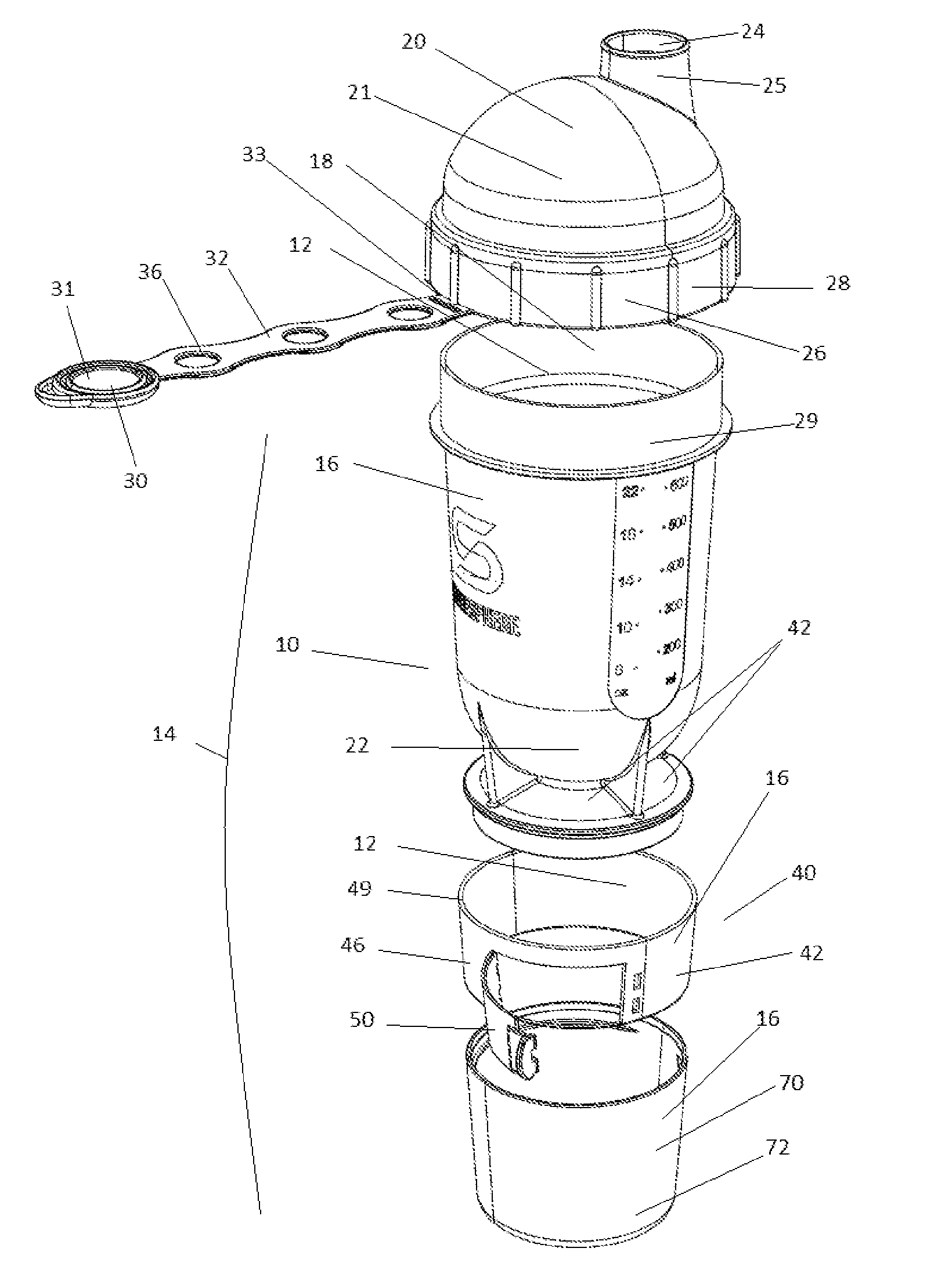
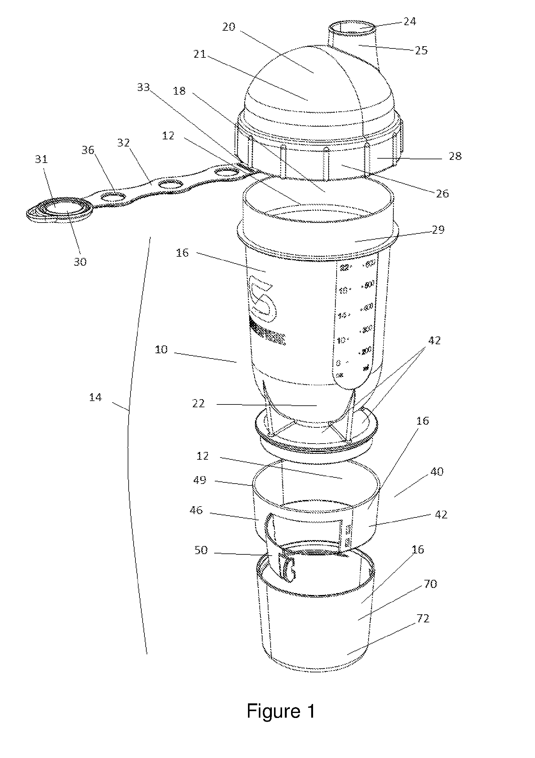
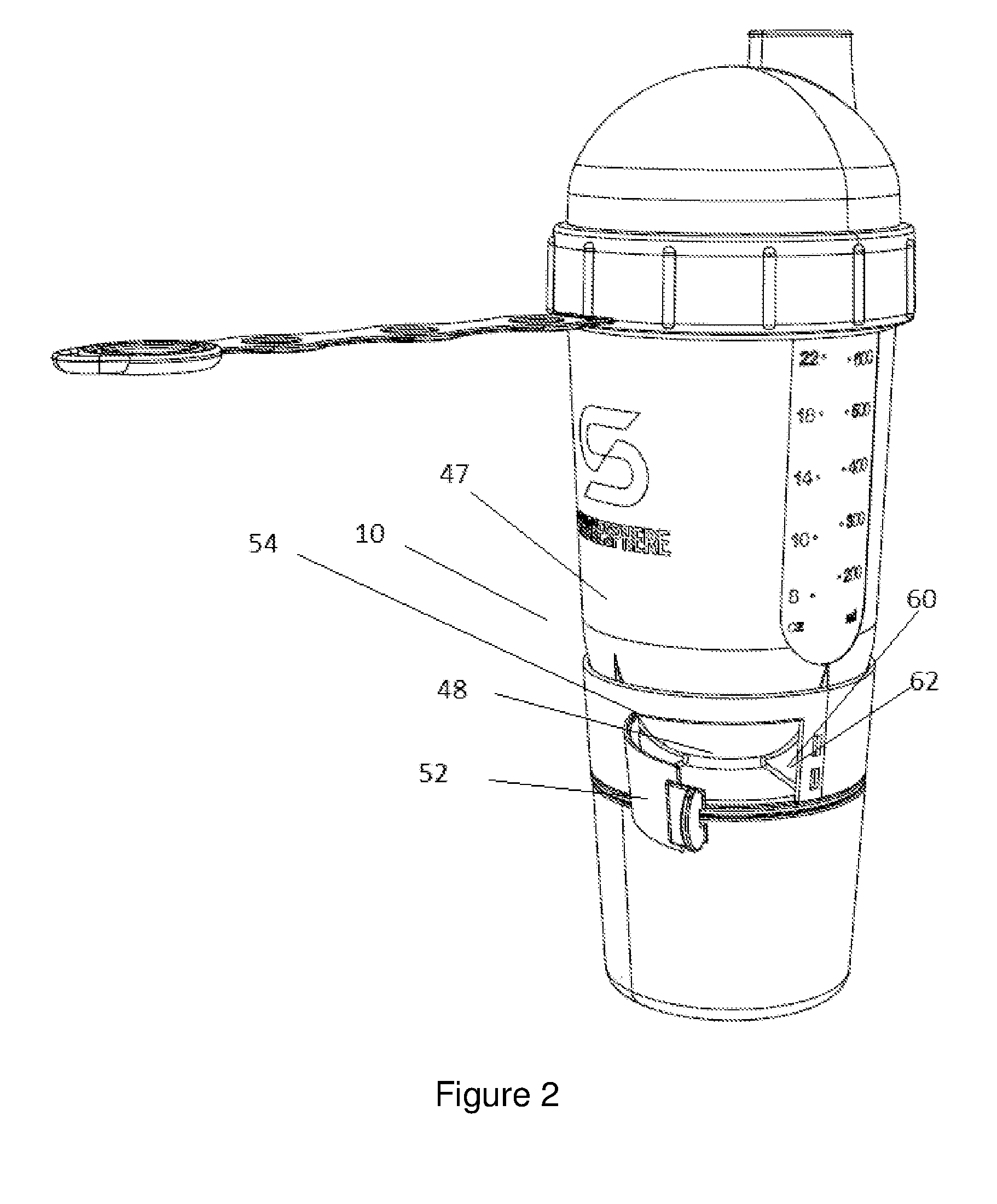
[0047]Referring to FIGS. 1 to 3 there is shown a sports bottle generally indicated at 10, which is in accordance with an embodiment of the present technology. Throughout this description, like numerals denote like parts. Therefore, referring to FIGS. 4 to 8 there is shown another sports bottle generally indicated at 110 in accordance with an embodiment of the present technology.

[0048]The sports bottle 10, 110 includes a hollow body 12, 112 comprising a housing 14, 114 having a peripheral wall 16, 116. There is also a cylindrical drink holding chamber 18, 118 inside the peripheral wall 16, 116, a plurality of mixing chambers 20, 120 in fluid communication with the drink holding chamber 18, 118, each one of the mixing chambers 20, 120 being hemispherical chambers 21, 121 (upper) and 22, 122 (lower) at opposed ends of the cylindrical drink holding chamber 18, 118.

[0049]In the embodiment shown at FIGS. 1 to 3 there is provided an outlet 24 for dispensing drink from the drink holding cha...


PUM


Abstract

A sports bottle is described. The bottle includes a hollow body comprising a housing having a peripheral wall, a cylindrical drink holding chamber inside the peripheral wall; a plurality of mixing chamber in fluid communication with the drink holding chamber, each one of the mixing chambers being hemispherical chambers at opposed ends of the cylindrical drink holding chamber; and an outlet for dispensing drink from the drink holding chamber, the outlet being disposed on an outside of one of the mixing chambers and in fluid communication therewith. Also described is a sports bottle including a hollow body comprising a housing having a peripheral wall, a drink holding chamber inside the peripheral wall; an outlet for dispensing drink from the drink holding chamber, the outlet being disposed on an outside of the peripheral wall and in fluid communication with the drink holding chamber, a hold for storing solid nutrition supplements, the hold comprising a plurality of supplement chambers being separated from the drink holding chamber and disposed within the peripheral wall; and a supplement chamber selector to facilitate access through the peripheral wall to a selected one or more of the supplement chambers.

Description

PRIORITY[0001]The present application claims priority to Australian application number AU2015100381, filed on Mar. 25, 2015, the entirety of which is hereby incorporated by reference.FIELD OF THE TECHNOLOGY[0002]The present technology relates generally to sports bottles, of the kind which accompany an athlete to a workout session at a gymnasium, track or field. The bottle also has particular application to the kitchen, for mixing dressings and mixtures having suspended solids.BACKGROUND OF THE TECHNOLOGY[0003]Known sports and / or mixing bottles generally include a main chamber closed by a threaded closure having a centrally-disposed outlet for dispensing a drink. The outlet may include a valve or closure for controlling the drink dispensing.[0004]To maintain very high performance, athletes consume diet and other training supplements in tablet and powder form, and when working out in high performance clothing have difficulty storing these supplements in a convenient place for consumpt...

Claims


Application Information

Patent Timeline
IPC IPC(8): B65D81/32B65D23/04
CPCB65D23/04B65D81/3222B65D25/56B65D81/3205B65D43/0231B65D47/148B65D2543/00046B65D2543/00092B65D2543/00351B65D2543/00537
Inventor BEARDSELL, RICK
Owner SHAKESPHERE PROD LTD
Learn More