Superconducting magnet system inlcuding thermally efficient ride-through system and method of cooling superconducting magnet system

a superconducting magnet and ride-through technology, which is applied in the direction of superconducting magnets/coils, magnetic bodies, domestic cooling apparatus, etc., can solve the problems of loss of cryocooler power, cryocooler malfunction, and loss of cryogenic fluid,

Active Publication Date: 2016-09-22
KONINKLJIJKE PHILIPS NV
View PDF5 Cites 13 Cited by
  • Summary
  • Abstract
  • Description
  • Claims
  • Application Information

AI Technical Summary

Benefits of technology

The present invention relates to a system for cooling a superconducting magnet using a cryogenic fluid. More specifically, the invention provides an apparatus that includes one or more gravity-fed cooling tubes and a heat exchanger for transferring heat from the cooling tubes to a second stage element. This system can effectively cool the magnet even in the event of a quench, which occurs when the cryocooler fails or malfunctions. The invention also includes a method for cooling the magnet using a cryofree system, which may not have means for user intervention. The technical effects of the invention include reducing the risk of damage to the magnet and minimizing the time and cost associated with recovery and repair.

Problems solved by technology

Unfortunately, it is possible that the power to the cryocooler may be lost, for example, during an electrical power outage due to a storm.
Furthermore, from time to time, the cryocooler may experience some malfunction or need to be turned off to perform maintenance.
This will cause some or all of the cryogenic fluid to evaporate and be lost.
Furthermore, the heat may damage the magnet and / or other components of the apparatus.
Furthermore, if heat from the quench caused the magnet or other components to be damaged, they may need to be repaired or replaced.
This recovery process can be expensive and time-consuming.
Typically, a trained technician must be dispatched to the facility (e.g., a medical center or hospital) where the superconducting magnet system is located and new cryogenic fluid (e.g. liquid helium), which may be quite costly, must be supplied to the cryostat.
Further, supplies of helium are becoming increasingly limited and so the cost of lost helium can significant.
Although this can be a significant problem in a typical superconducting magnet system for an MRI apparatus, the problem can be at least somewhat ameliorated by the fact that such superconducting magnet systems typically employ a relatively large volume of cryogenic fluid (e.g., 1000 liters of liquid helium).
The large volume of cryogenic fluid has a large thermal mass which may mean that power must be lost for a relatively long time—maybe even days—before the temperature of the magnet reaches the critical temperature and produces a quench.
However, some newer MRI apparatuses are being developed and deployed which employ so-called “cryofree” superconducting magnet systems which are closed or sealed and which may not include means for a user to add new cryogenic material to the system.
Accordingly, a quench in a cryofree or sealed superconducting magnet system may occur in only 30 minutes or less after the cryocooler suffers a loss of electrical power or some malfunction, or undergoes maintenance, which prevents it from operating properly and maintaining the temperature in the cryostat to be near absolute zero.
Furthermore, since no means is typically provided for a user to add new cryogenic material to the system, if the cryogenic fluid is degraded or evaporated due to a quench, then recovery may require days or weeks.

Method used


Image

  • Superconducting magnet system inlcuding thermally efficient ride-through system and method of cooling superconducting magnet system
  • Superconducting magnet system inlcuding thermally efficient ride-through system and method of cooling superconducting magnet system
  • Superconducting magnet system inlcuding thermally efficient ride-through system and method of cooling superconducting magnet system

Examples


Embodiment Construction

[0035]The present invention will now be described more fully hereinafter with reference to the accompanying drawings, in which embodiments of the present invention are shown. The present invention may, however, be embodied in different forms and should not be construed as limited to the embodiments set forth herein. Rather, these embodiments are provided as teaching examples of the invention. Within the present disclosure and claims, when something is said to have approximately a certain value, then it means that it is within 10% of that value, and when something is said to have about a certain value, then it means that it is within 25% of that value. When something is said to be substantially greater, then it means that it is at least 10% greater, and when something is said to be substantially less, then it means that it is at least 10% less.

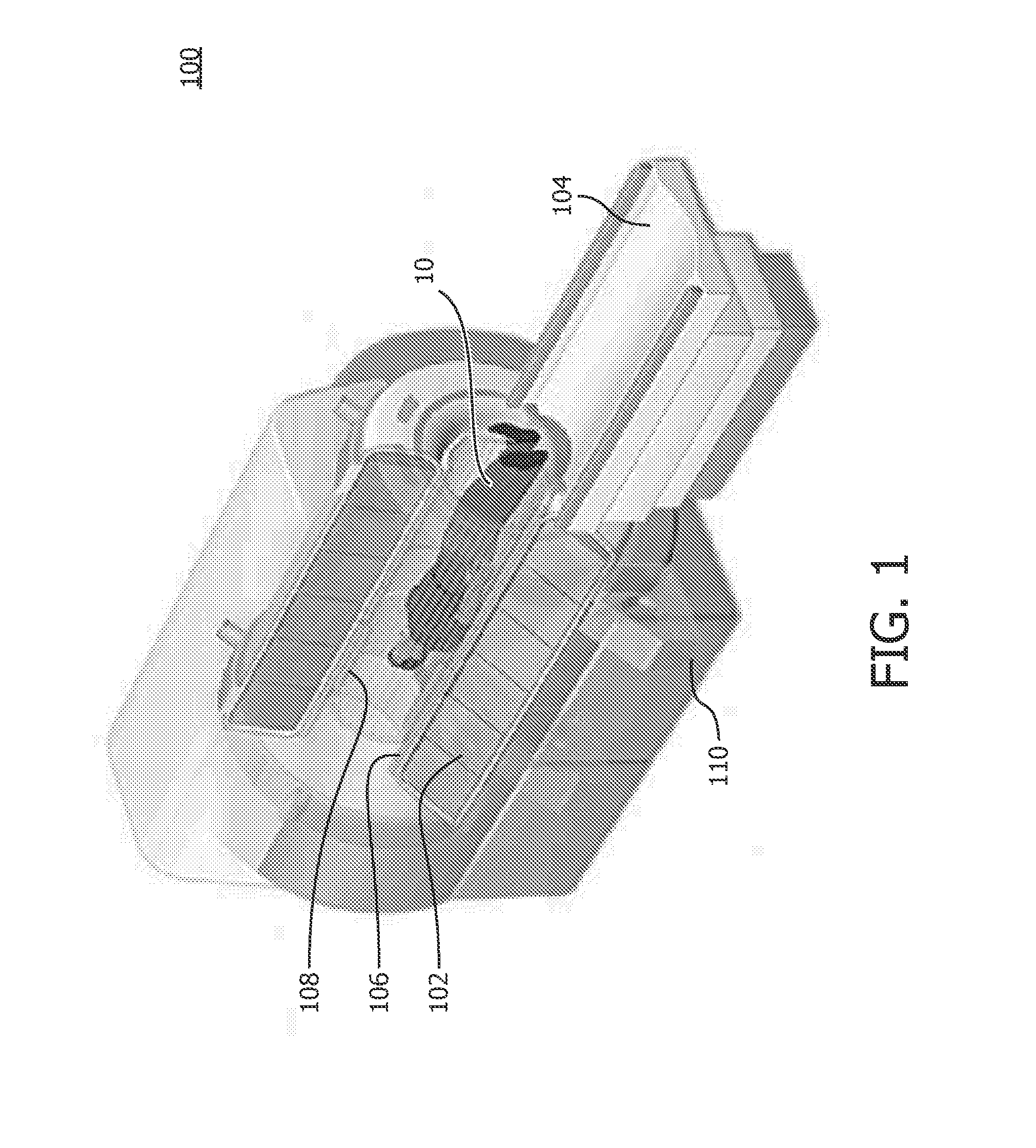
[0036]FIG. 1 illustrates an exemplary embodiment of a magnetic resonance imaging (MRI) apparatus 100. MRI apparatus 100 may include a magnet 1...


PUM


Abstract

A superconducting magnet system, including a cryostat, and a ride-through system for the superconducting magnet system include: one or more gravity-fed cooling tubes configured to have therein a cryogenic fluid; a first heat exchanger configured to transfer heat from the one or more gravity-fed cooling tubes to a cryocooler; a storage device having an input connected to the first heat exchanger and configured to receive and store a boiled-off gas from the first heat exchanger; and a thermal regenerator having an input connected to the output of the storage device.

Description

TECHNICAL FIELD[0001]The present invention generally pertains to superconducting magnet systems and cryostats for superconducting magnet systems. In particular, the present invention is related to a ride-through system for cooling a superconducting magnet system, a superconducting magnet system which includes such a ride-through system, and a method of cooling a superconducting magnet system.BACKGROUND AND SUMMARY[0002]Superconducting magnets are used in a variety of contexts, including nuclear magnetic resonance (NMR) analysis, and magnetic resonance imaging (MRI). To realize superconductivity, the superconducting magnet is maintained in a cryogenic environment at a temperature near absolute zero. Typically, the superconducting magnet includes one or more electrically conductive coils which are disposed in a cryostat containing a substantial volume of a cryogenic fluid such as liquid helium. Many such superconducting magnets operate in “persistent mode.” A superconducting magnet wh...

Claims


Application Information

Patent Timeline
IPC IPC(8): H01F6/04H01F6/02A61B5/055H01F6/06
CPCH01F6/04A61B5/0555H01F6/02H01F6/06G01R33/3804G01R33/3815F25B9/10F25D19/006A61B5/055
Inventor ACKERMANN, ROBERT ADOLPHPFLEIDERER, GLEN GEORGEJONAS, PHILIP ALEXANDERVOSS, MATTHEW
Owner KONINKLJIJKE PHILIPS NV
Why Eureka
Try Eureka