
Method for creating a camera capture effect from user space in a camera capture system

a camera capture and user space technology, applied in the field of digital cameras, can solve the problems of inability to obtain information from lower layer hardware devices such as sensors, incompatible solutions, and high cost, and achieve the effect of avoiding the need for a solution, and ensuring the effect of a user spa

Active Publication Date: 2016-09-15
SAMSUNG ELECTRONICS CO LTD
View PDF11 Cites 6 Cited by
  • Summary
  • Abstract
  • Description
  • Claims
  • Application Information

AI Technical Summary

Benefits of technology

The patent text describes a method for creating a "refocus effect" in a captured image. This allows the user to select the specific part of the image they want to focus on after the capture. The text also suggests using the "technical effects" of the capture scene to create a more interesting and unique image.

Problems solved by technology

While the visual impact of the refocus effect is quite significant and it completely disrupts the photo shooting paradigm from a consumer's perspective, the means does not justify the ends.
Further, such solutions are expensive and are not compatible with existing image capture devices / cameras and a new device or array of lenses / sensors would be required essentially to produce this refocus effect.
Although there have been attempts to simulate the refocus effect by using techniques that require some form of additional hardware, hardware add-ons or obtaining information from lower layer hardware devices (such as sensors) might not always be available.
All these again compromise on cost or device compatibility.
Other limitations of the related art will become apparent upon reading of the specification and a study of the drawings.

Method used


Image

  • Method for creating a camera capture effect from user space in a camera capture system
  • Method for creating a camera capture effect from user space in a camera capture system
  • Method for creating a camera capture effect from user space in a camera capture system

Examples


Embodiment Construction

[0039]The present invention provides a method and system for capturing a refocusable image set. In the following detailed description of the embodiments of the invention, reference is made to the accompanying drawings that form a part hereof, and in which are shown by way of illustration specific embodiments in which the invention may be practiced. These embodiments are described in sufficient detail to enable those skilled in the art to practice the invention, and it is to be understood that other embodiments may be utilized and that changes may be made without departing from the scope of the present invention. The following detailed description is, therefore, not to be taken in a limiting sense, and the scope of the present invention is defined only by the appended claims.

[0040]Most of the image-capture devices available in the market today, i.e. cameras present in digital cameras, smartphones, tablets, are equipped with the ability to explicitly set the focus region before taking...


PUM


Abstract

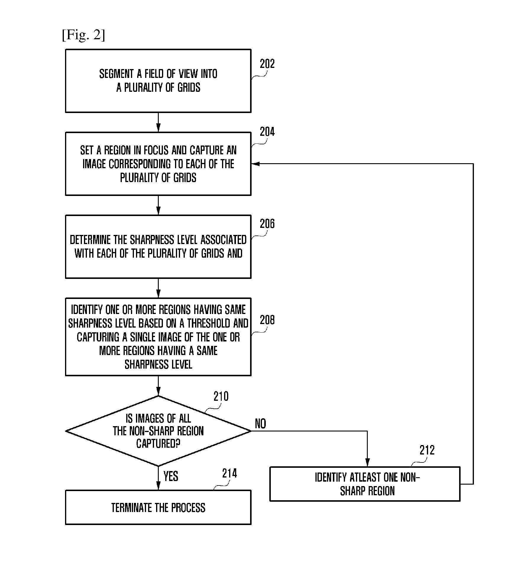
The various embodiments of the present invention disclose an image processing method and system for capturing a refocusable image set. The method comprises of segmenting a field of view into a plurality of grids, determining a sharpness level associated with each of the plurality of grids, identifying one or more regions based on the determined sharpness level of each of the plurality of grids, each region comprising one or more of the plurality of grids and capturing an image associated with each of the identified one or more regions to form the refocusable image set. The method further comprises of detecting a refocusing action on an object, in the field of view, having an associated illumination level and varying the associated illumination level of the object based on the detection.

Description

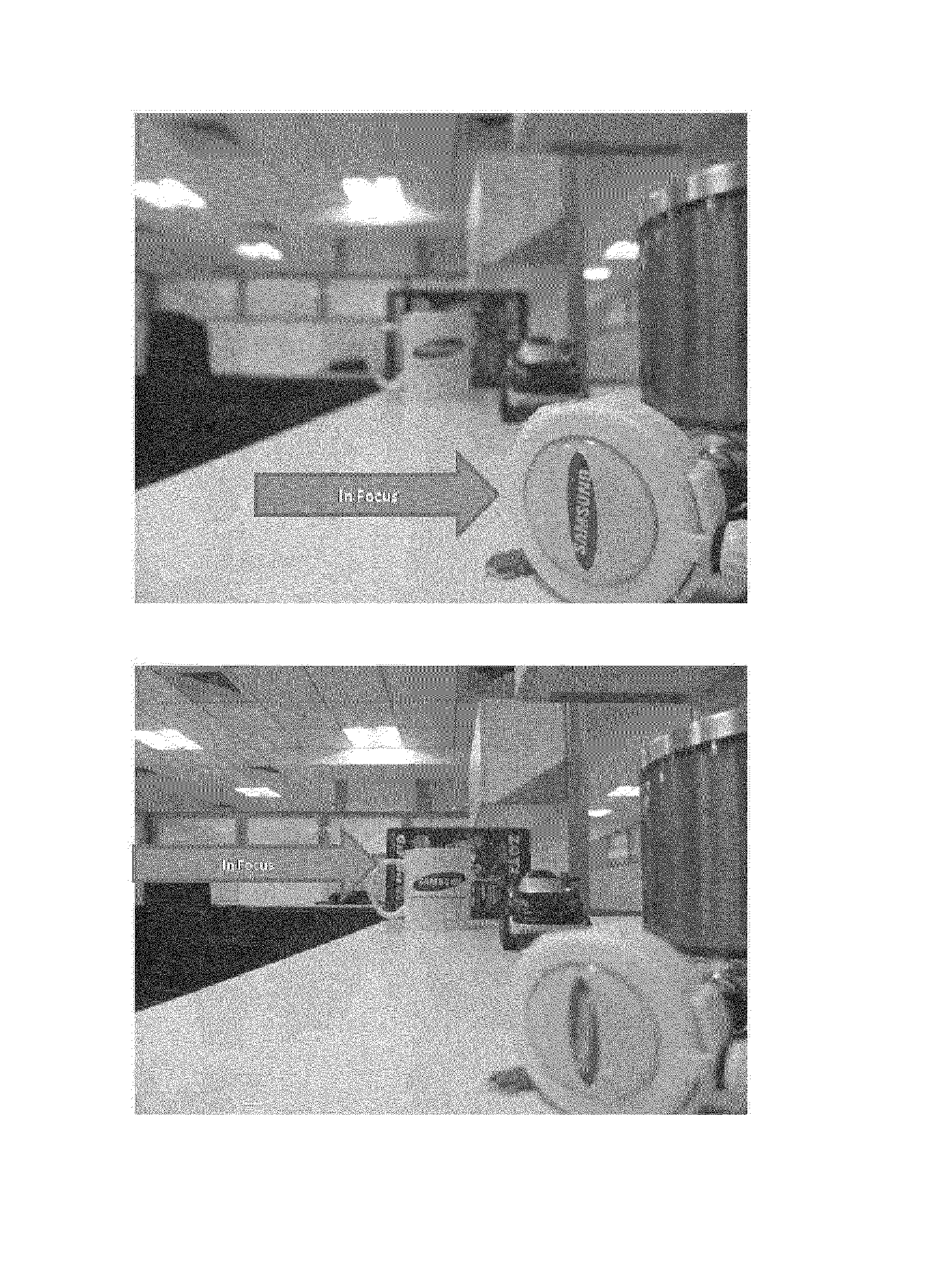
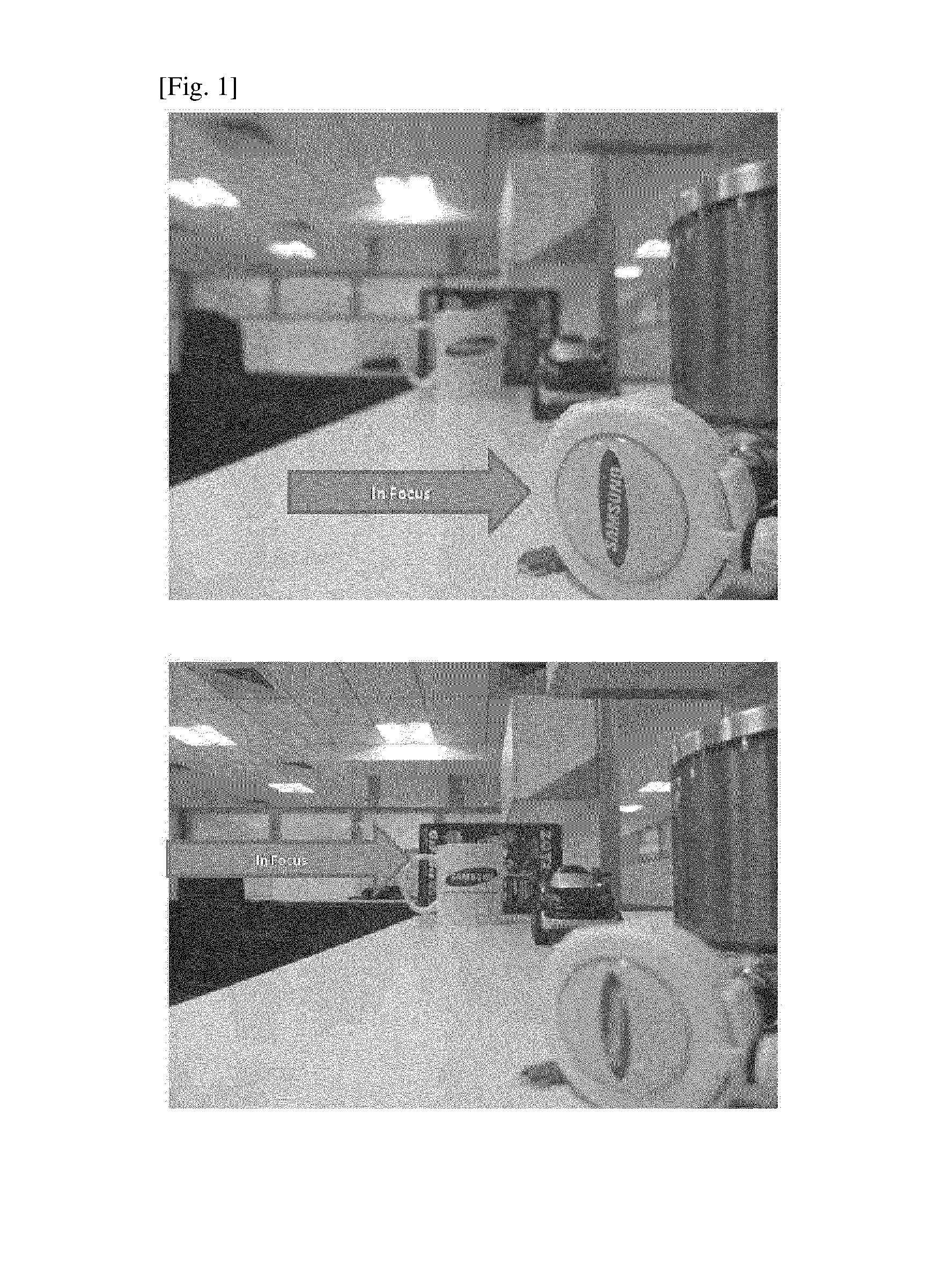
TECHNICAL FIELD[0001]The present invention generally relates to image processing systems and methods and particularly to digital cameras that employ a plenoptic imaging method and system for creating a refocusable effect after capturing the image.BACKGROUND ART[0002]Light field cameras or plenoptic cameras are ones that use an array of micro lenses to capture 4-dimensional light field information about a scene. This method of capture gathers a lot of information about the scene that a variety of computer vision and graphics applications can exploit. One such technique or effect presently rolled out by commercial plenoptic cameras is the ability to refocus an image that is already shot. Incidentally, the refocus effect as illustrated in FIG. 1 appears to be the sole selling point in contemporary commercial light field cameras. Alternatively light field cameras offer end-users the ability to shoot a given scene and then refocus into regions of their interest.[0003]While the visual imp...

Claims


Application Information

Patent Timeline
IPC IPC(8): G02B7/38H04N5/235G06T5/00H04N5/232
CPCG02B7/38H04N5/23212G06T5/003H04N5/2355H04N5/2356H04N5/23238G02B7/36G06T2207/10152H04N23/673H04N23/951H04N23/741H04N23/743G06T5/73H04N23/698
Inventor NARAYANAN, KARTHIKCHIRANJEEVI, BHUPALA SRIVARMAKIM, GOUNYOUNGNARAYANASWAMY, SANTHOSH KUMAR BANADAKOPPAPATTANAYAK, DEEPANSHU
Owner SAMSUNG ELECTRONICS CO LTD
Learn More