Cranial plating and bur hole cover system and methods of use
a technology of cranial surface and bur hole cover, which is applied in the field of cranial closure improvements, can solve the problems of palpable and often visible protrusions, gross external deformation, and distressing patient's accompanying discomfort from rubbing, so as to minimize the cranial surface profile, improve the effect of cranial closure, and reduce the protrusions
- Summary
- Abstract
- Description
- Claims
- Application Information
AI Technical Summary
Benefits of technology
Problems solved by technology
Method used
Image
Examples
example 1
Cranial Plating Device Design Variations
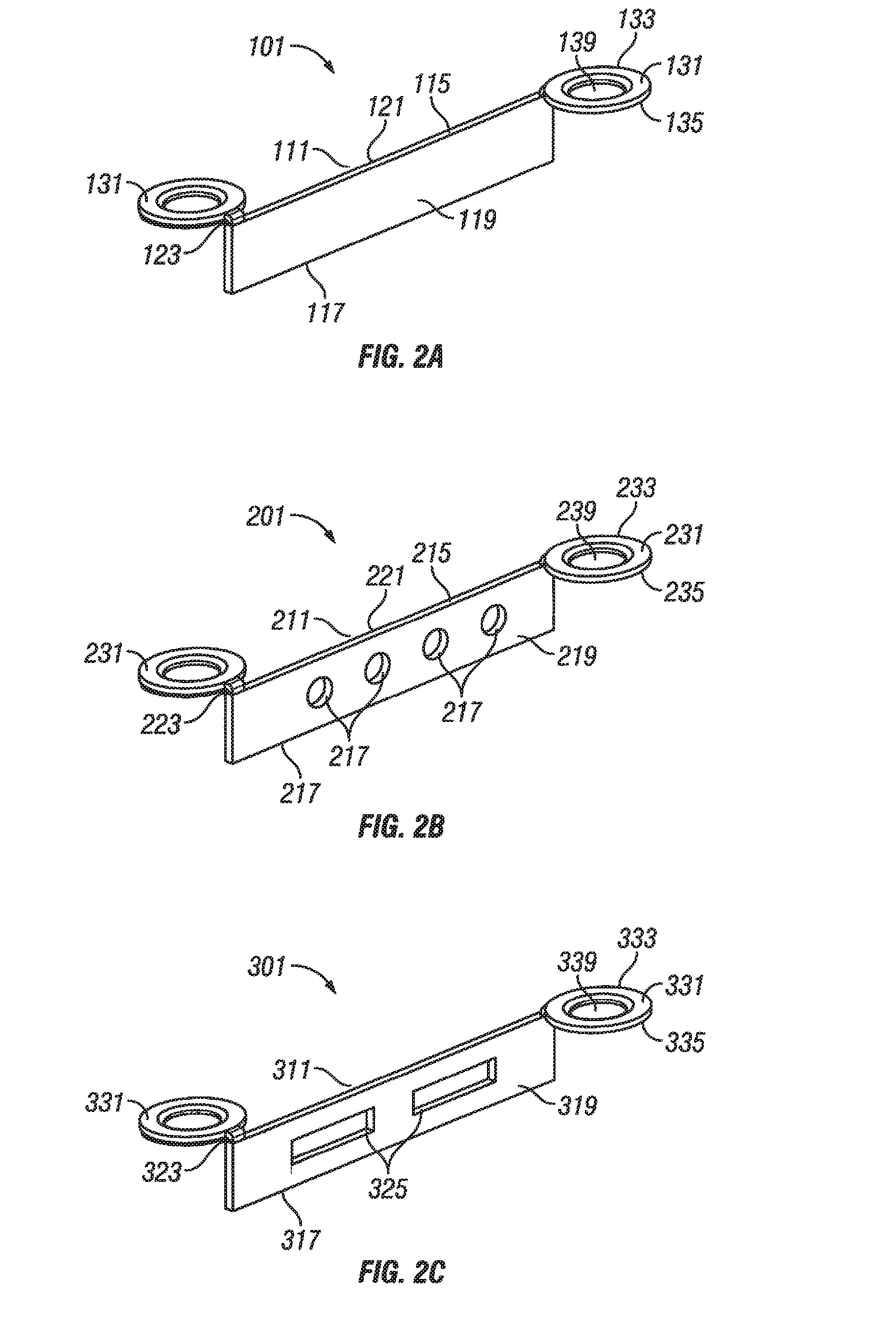
[0072]The kerf cranial closure device contemplated will feature many of the following properties which may optimize cranial closure performance:
[0073]1) The design is intended to specifically close the bony defect made in the skull by any of the common commercially available craniotomes, known as the kerf;
[0074]2) The keel portion of the cranial plate shall reside within the kerf;
[0075]3) The cranial plate fixation wings shall be on opposing sides of each other in relation to the keel;
[0076]4) The cranial plate fixation wings shall have a tapered fixation aperture which allows for the placement of a tapered fixation screw to reside flush within the cranial plate wing and allows for the thread of the fixation screw to secure into the cranium and flap;
[0077]5) The keel portion should be flexible or bendable, and / or manufactured with specific angles or curves to allow for the variability for closing various kerf configurations;
[0078]6) The keel p...
example 2
Tooling Embodiments
[0080]The tooling system may comprise of an impression device which is a high-powered drill which consists of the cylindrical or disc-like bur (drill-bit) and the surrounding guide, the drill-bit is meant to be applied end on into the bone to make semicircular depression in the bone comprising a ⅗ to almost one whole circle that has a central point to allow the bit to bite bone at a precise spot this will also serve to create a pilot hole for screw when the plate is applied.
[0081]Another embodiment of the tooling system comprises the use of a guide the guide covers all the drill-bit except the last 0.4 to 0.7 mm the disc section the guide will prevent the drill-bit from cutting too deep when the guide tip rests on the bone, the impression made is at the proper depth to receive the plate. The guide has a two orientation posts or an orientation ridge, that are rested at the edge of the bone to assure that the impressions made at the edge of the bone are at the prope...
example 3
Exemplary Method of Using an Embodied Cranial Plating System
Cranial Defect
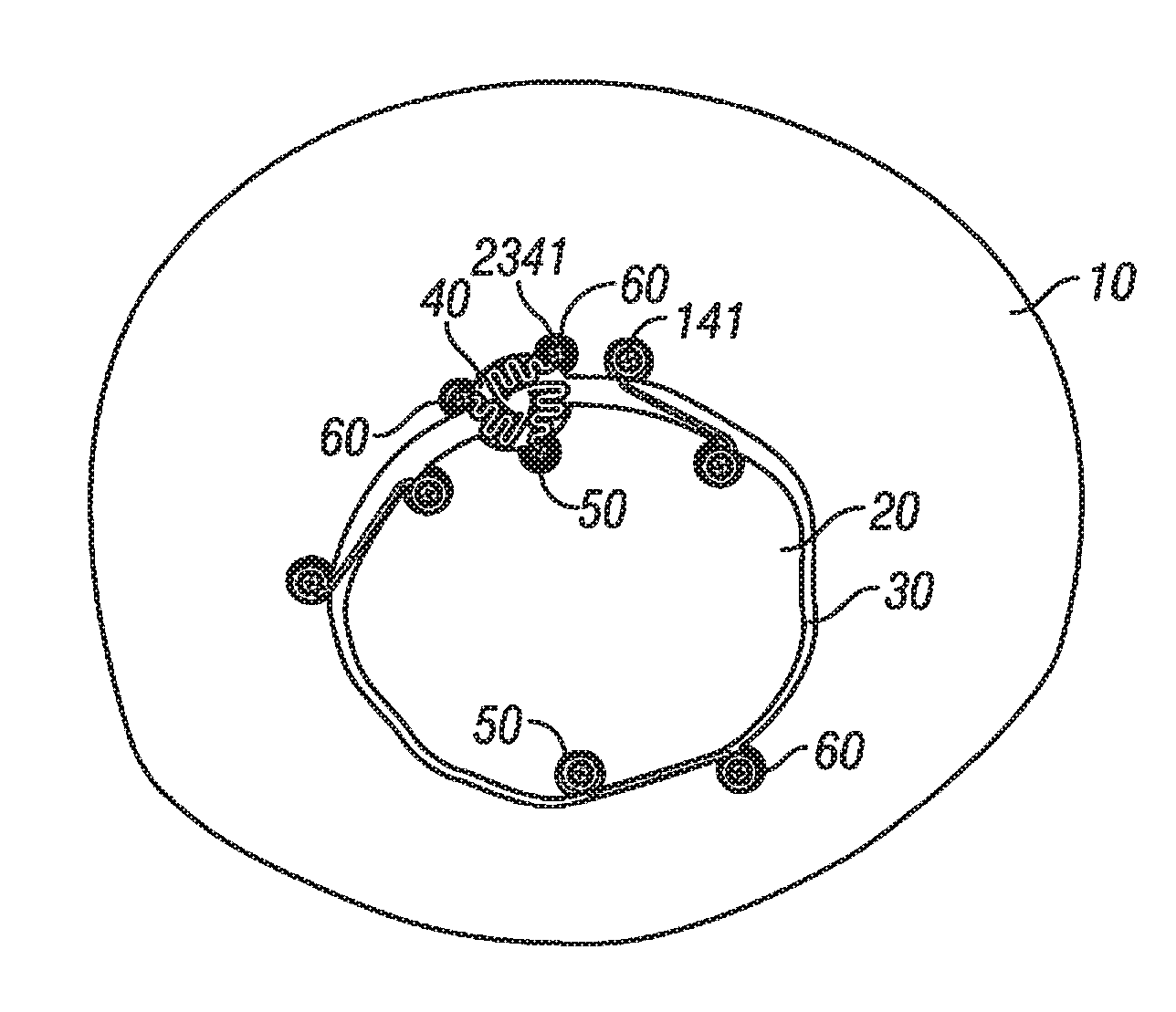
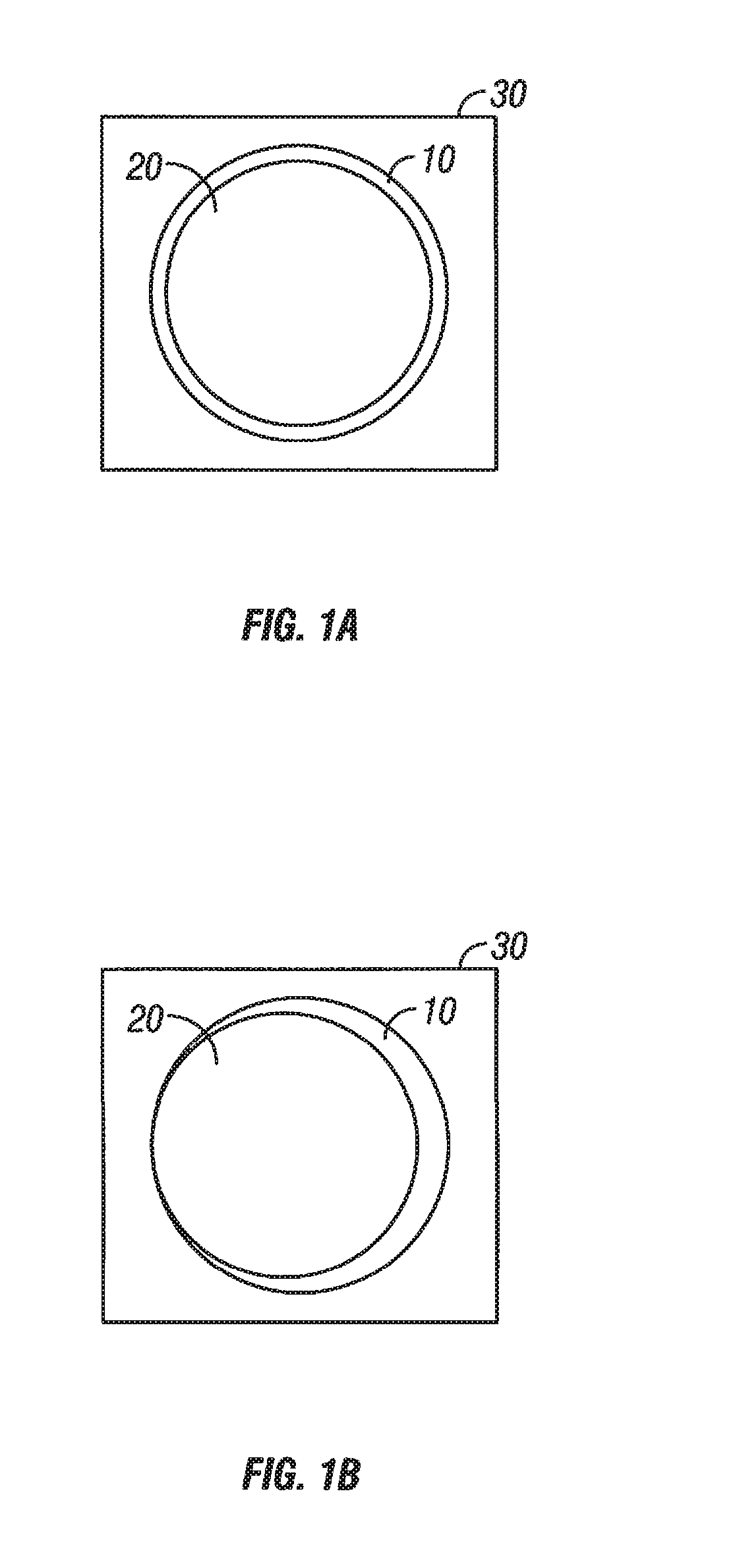
[0082]In the creation of a craniotomy, the bone is opened from its external surface to the level of the dura by placement of one or more bur holes, made either freehand with a high-speed drill or with a cranial perforator. The bur holes are connected with a high speed drill router (craniotome footplate attachment), which creates a trough in the bone, known as the kerf.
Closure of Cranium
[0083]At the conclusion of the intracranial part of the operation, the free bone flap is typically secured to the surrounding cranium with a fixation device in which pilot holes are drilled in the cranial flap and a plurality of fixation devices are attached to the cranial flap with screws inserted into the pilot holes, then the cranial flap is placed back into the cranial opening, and positions for attachment of the fixation devices is measured and marked with an awl, and a pilot hole is drilled into the cranium and the fixatio...
PUM
 Abstract
Description
Claims
Application Information
 - R&D
- Intellectual Property
- Life Sciences
- Materials
- Tech Scout
- Unparalleled Data Quality
- Higher Quality Content
- 60% Fewer Hallucinations
Browse by: Latest US Patents, China's latest patents, Technical Efficacy Thesaurus, Application Domain, Technology Topic, Popular Technical Reports.
© 2025 PatSnap. All rights reserved.Legal|Privacy policy|Modern Slavery Act Transparency Statement|Sitemap|About US| Contact US: help@patsnap.com


