Quantum tube, backlight module and liquid crystal display device

a backlight module and liquid crystal display technology, applied in the field ofquantum tubes, to achieve the effect of enhancing light utilization rate, uniform light emitting efficiency and life of light sources of backlight modules

Active Publication Date: 2016-09-08
HANNSTAR DISPLAY NANJING +1
View PDF7 Cites 2 Cited by
  • Summary
  • Abstract
  • Description
  • Claims
  • Application Information

AI Technical Summary

Benefits of technology

The invention is about a new way to improve the efficiency and lifespan of light sources in a backlight module used in liquid crystal displays. It involves placing a quantum tube with inclined parts between a light guide plate and the light sources, and adding two types of fluorescent particles to the quantum tube. This arrangement allows the light sources to emit different colored lights, and the fluorescent particles to convert the first color light into a second color light without contacting the light sources directly. This prevents heat-related damage to the fluorescent particles and increases the overall light utilization rate. The inclined part of the quantum tube also helps guide the light emitted by the light sources to the light emitting surface, further enhancing the efficiency of the backlight.

Problems solved by technology

How to improve environmental protection (e.g. do not use color filter) and display quality (e.g. Motion Picture Response Time (MPRT)) is a significant issue for a liquid crystal display device.

Method used


Image

  • Quantum tube, backlight module and liquid crystal display device
  • Quantum tube, backlight module and liquid crystal display device
  • Quantum tube, backlight module and liquid crystal display device

Examples


first embodiment

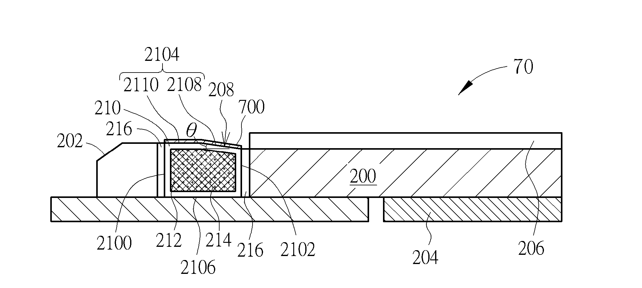
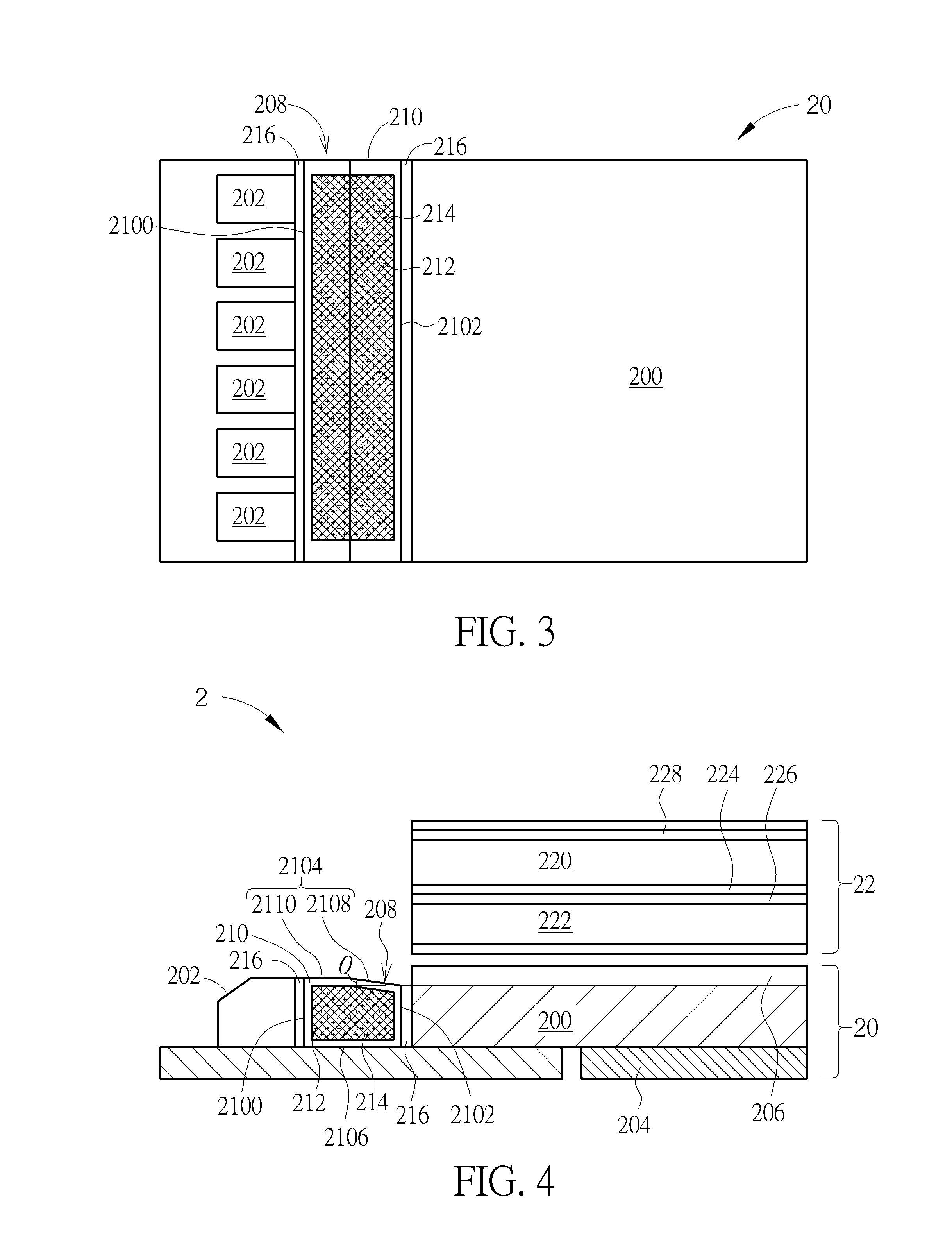
[0033]Referring to FIGS. 3 and 4, FIG. 3 is a schematic top view illustrating a backlight module 20 according to the invention and FIG. 4 is a schematic sectional view illustrating a liquid crystal display device 2 equipped with the backlight module 20 shown in FIG. 3. As shown in FIG. 4, the liquid crystal display device 2 comprises a backlight module 20 and a liquid crystal display panel 22, wherein the liquid crystal display panel 22 is disposed on the backlight module 20. In this embodiment, the liquid crystal display panel 22 may have a liquid crystal 224 and a thin film transistor (TFT) driving circuit 226 located between an upper substrate 220 and a lower substrate 222. Furthermore, the liquid crystal display panel 22 may further has a touch sensing circuit 228 formed on the upper substrate 220, so as to achieve touch function.

[0034]As shown in FIGS. 3 and 4, the backlight module 20 comprises a light guide plate 200, a plurality of light sources 202, a reflective sheet 204, a...

second embodiment

[0038]Referring to FIG. 5, FIG. 5 is a schematic top view illustrating a backlight module 30 according to the invention. The main difference between the backlight module 30 and the aforesaid backlight module 20 is that, in the backlight module 30, the light incident surface 2100 of the quantum tube 208 is a flat surface and the light emitting surface 2102 of the quantum tube 208 is a concave arc-shaped surface. In this embodiment, when the light emitted by the light sources 202 passes through the light emitting surface 2102, which is formed as concave arc-shaped surface, and enters the light guide plate 200, the light will be concentrated inwardly, so as to enhance central luminance of the backlight module 30 effectively.

third embodiment

[0039]Referring to FIG. 6, FIG. 6 is a schematic top view illustrating a backlight module 40 according to the invention. The main difference between the backlight module 40 and the aforesaid backlight module 20 is that, in the backlight module 40, the light incident surface 2100 of the quantum tube 208 is a flat surface and the light emitting surface 2102 of the quantum tube 208 is a convex arc-shaped surface. In this embodiment, when the light emitted by the light sources 202 passes through the light emitting surface 2102, which is formed as convex arc-shaped surface, and enters the light guide plate 200, the light will be diffused outwardly, so as to make display quality of the liquid crystal display device more uniform.


PUM


Abstract

A quantum tube includes a tube body, a plurality of first fluorescent particles and a plurality of second fluorescent particles. The tube body has a light incident surface, a light emitting surface, a top surface and a bottom surface. The top surface is connected between the light incident surface and the light emitting surface. The bottom surface is connected between the light incident surface and the light emitting surface. The top surface is opposite to the bottom surface. The top surface has an inclined portion. The inclined portion inclines with respect to the bottom surface by an angle. The first fluorescent particles are disposed in the tube body. The second fluorescent particles are disposed in the tube body.

Description

BACKGROUND OF THE INVENTION[0001]1. Field of the Invention[0002]The invention relates to a quantum tube and, more particularly, to a quantum tube having an inclined portion, a backlight module equipped with the quantum tube, and a liquid crystal display device equipped with the backlight module.[0003]2. Description of the Prior Art[0004]How to improve environmental protection (e.g. do not use color filter) and display quality (e.g. Motion Picture Response Time (MPRT)) is a significant issue for a liquid crystal display device. If a high-speed liquid crystal can be used in the liquid crystal display device, the environmental protection and display quality can be improved. A blue phase liquid crystal is a liquid crystal with high-speed reaction, whose rising time and falling time are within one millisecond. The high-speed liquid crystal can improve serious motion blur for the liquid crystal display device. A field sequential color (FSC) method is a display technology without using a c...

Claims


Application Information

Patent Timeline
IPC IPC(8): F21V8/00F21V9/40
CPCG02B6/0025G02B6/0023
Inventor LIU, CHUN-PINLIN, CHIN-WEI
Owner HANNSTAR DISPLAY NANJING
Why Eureka
Try Eureka