
One-way clutch

a one-way clutch and clutch technology, applied in couplings, machines/engines, engine starters, etc., can solve the problems of limited relative rotation between the two rotational members of one-way clutches in one direction, and inability to obtain appropriate bolt fastening for

Inactive Publication Date: 2016-09-08
TOYOTA JIDOSHA KK
View PDF4 Cites 1 Cited by
  • Summary
  • Abstract
  • Description
  • Claims
  • Application Information

AI Technical Summary

Benefits of technology

This patent describes a one-way clutch that can be easily assembled with a rotational body and fixed in place with a bolt. The clutch prevents the rotation of a second rotational member in a certain direction. The first rotational body is fixed and has a screw hole into which a bolt is inserted, while the second rotational member has a hole through which the bolt passes. The design of the holes ensures that the bolt is easily inserted and fits securely. This improves the assembly process of the one-way clutch with the rotational body.

Problems solved by technology

When the bolt is fastened in a state where the phase of the bolt hole and the phase of the screw hole are not coincided with each other, the screw hole and a screw head of the bolt possibly interfere with each other, and thus an appropriate bolt fastening force cannot possibly be obtained.
In particular, in the case where the one-way clutch is used as the brake mechanism as described above, relative rotation between the two rotational members of the one-way clutch is limited to the one direction.
Thus, also in this case, the appropriate bolt fastening force cannot possibly be obtained.

Method used


Image

  • One-way clutch
  • One-way clutch
  • One-way clutch

Examples


Embodiment Construction

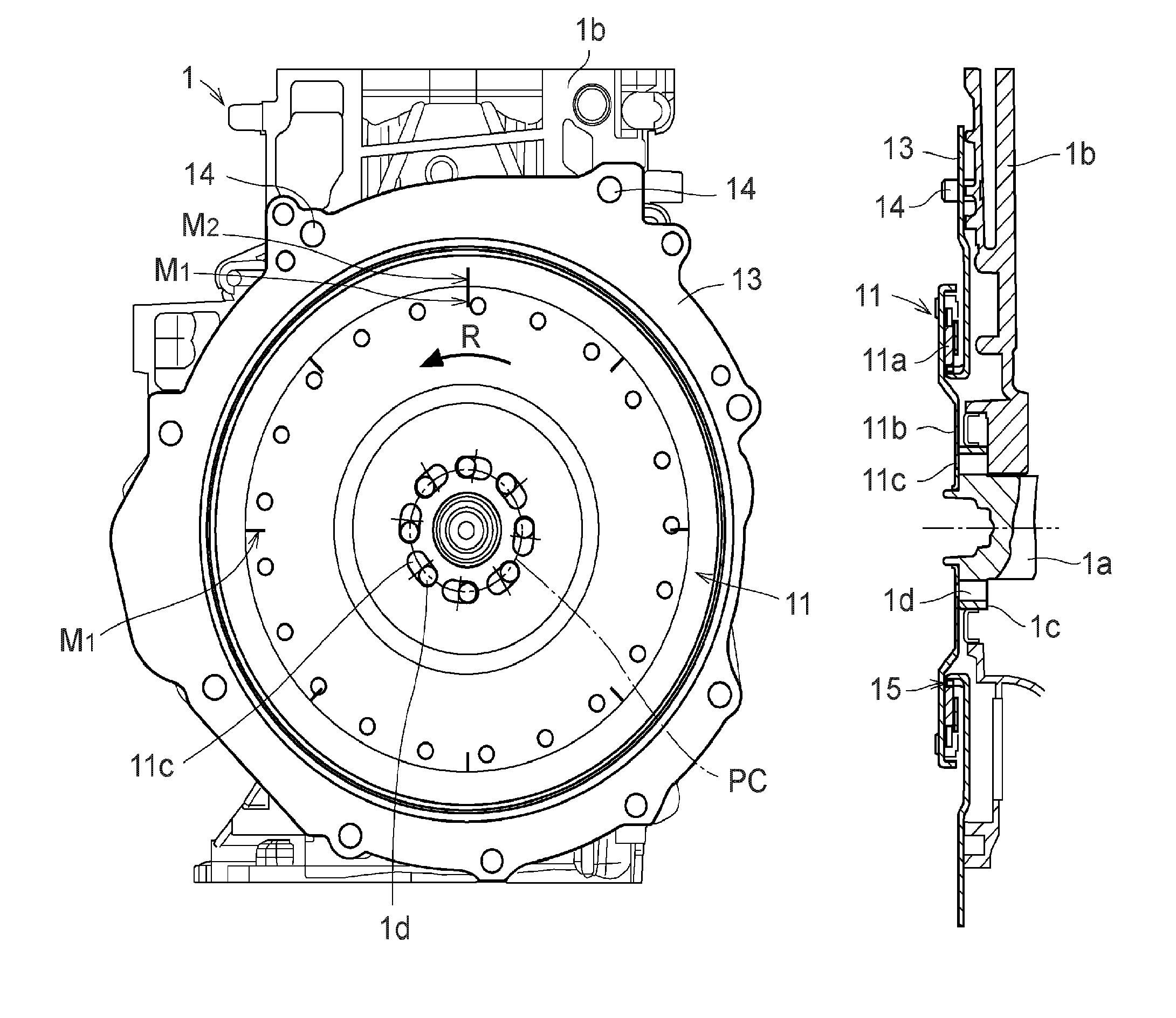
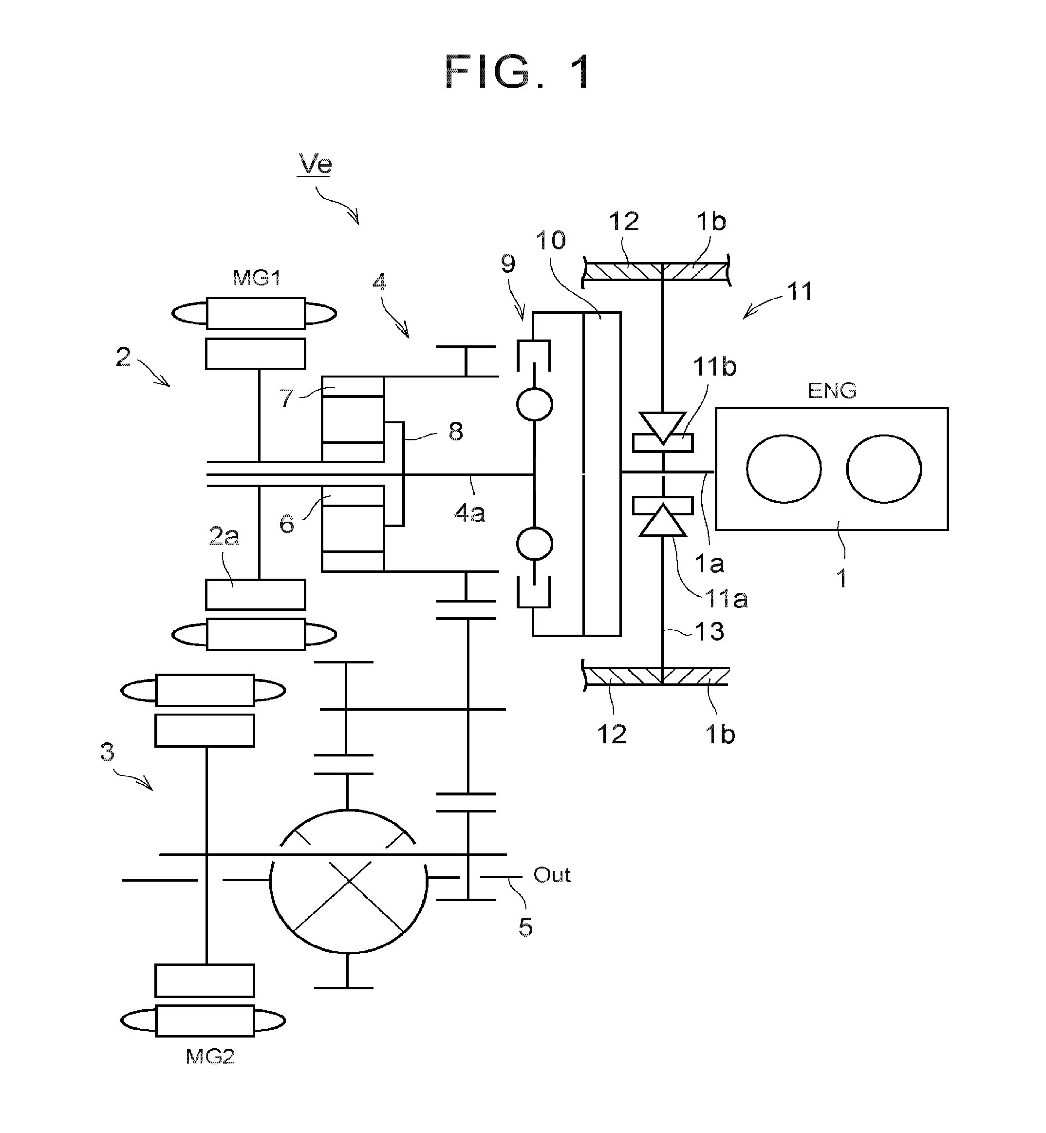
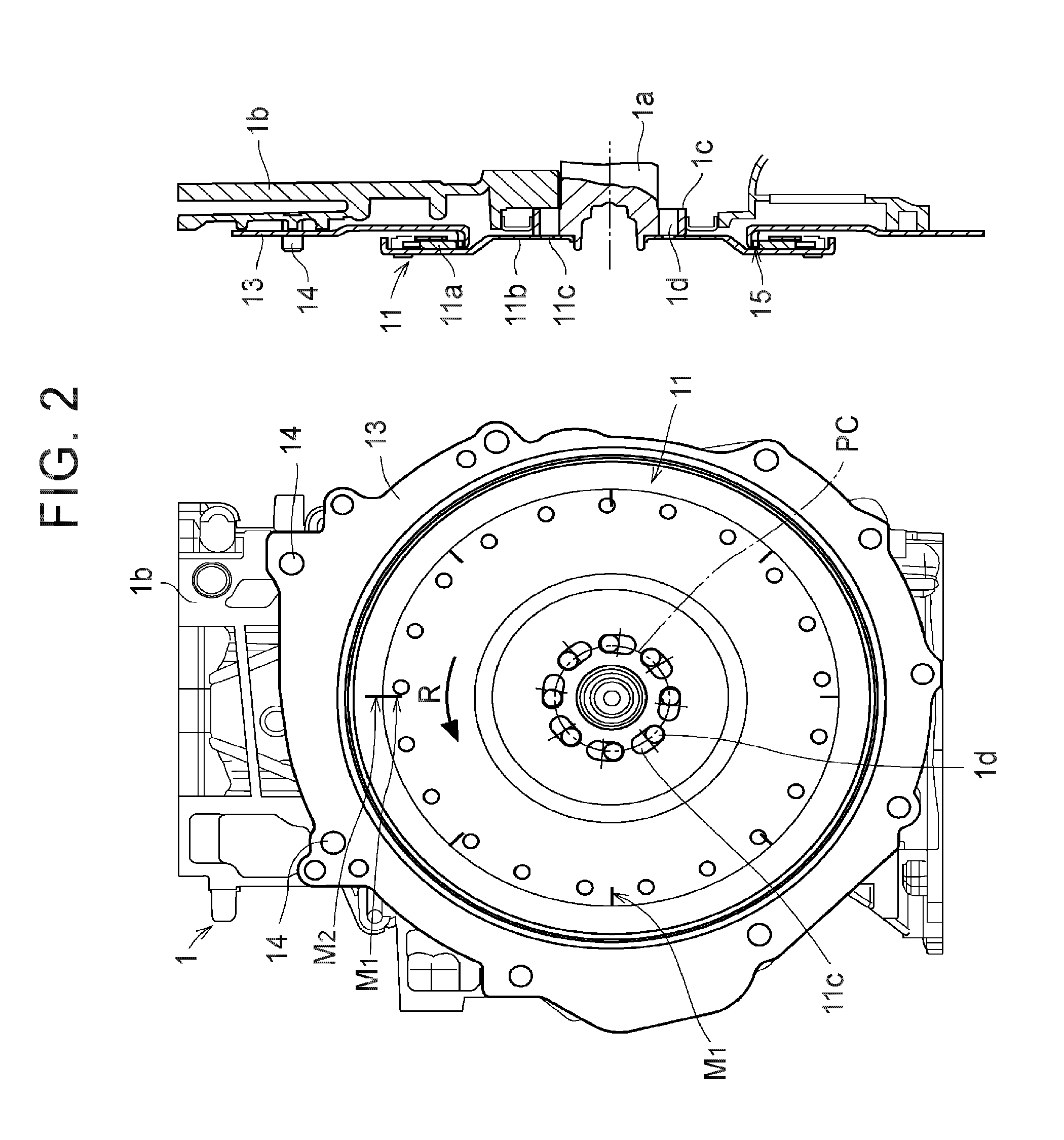
[0027]Next, this disclosure will specifically be described with reference to the drawings. One example of a vehicle Ve that uses a one-way clutch as a target of this disclosure is shown in FIG. 1. The vehicle Ve is a hybrid vehicle in which an engine (ENG) 1, a first motor (MG1) 2, and a second motor (MG2) 3 as drive power sources are mounted. This vehicle Ve is configured to divide power output by the engine 1 by a power split mechanism 4 and transmit the power to the first motor 2 and a drive shaft 5. In addition, the vehicle Ve is configured to drive the second motor 3 by electric power that is generated by the first motor 2 and be able to add power output by the second motor 3 to the drive shaft 5.

[0028]The power split mechanism 4 is constructed of a planetary gear unit that has a sun gear 6, a ring gear 7, and a carrier 8, for example. In this example shown in FIG. 1, a planetary gear unit of a single pinion type is used. The planetary gear unit, which constitutes this power sp...


PUM


Abstract

A one-way clutch includes a first rotational member, a second rotational member, and a first rotational body. The second rotational member has plural first through holes in which bolts are inserted. A dimension of the first through hole in a circumferential direction is larger than a dimension of the first through hole in a radial direction. A first region and a second region are obtained by dividing the first through hole into two regions in the circumferential direction. The first region is located ahead of the second region in a rotatable direction of the second rotational member. The bolts are inserted such that the each of the bolts is located in the first region of the first through hole, and the second rotational member and the first rotational body are fastened by the bolts.

Description

INCORPORATION BY REFERENCE[0001]The disclosure of Japanese Patent Application No. 2015-043232 filed on Mar. 5, 2015 including the specification, drawings and abstract is incorporated herein by reference in its entirety.BACKGROUND[0002]1. Field[0003]This disclosure relates to a one-way clutch that is used as a brake mechanism for fixing either one of two rotational members that rotate relative to each other and thereby allowing rotation of the either one of the two rotational members in one rotational direction while restricting rotation thereof in the other rotational direction.[0004]2. Description of Related Art[0005]A one-way clutch can function as a brake mechanism for unrotatably fixing either one of two rotational members of the one-way clutch that rotate relative to each other and thereby restricting rotation of the either one of the two rotational members in only one direction. For example, a rotational direction of a rotational body, such as an output shaft of an engine or a...

Claims


Application Information

Patent Timeline
IPC IPC(8): F16D41/18
CPCF16D41/185F02N11/006F02N15/027F16D41/12F16D2300/12F02N15/023F16D1/076F16D1/12F16D41/02F16D41/06B60K6/383B60K6/445F02N15/046Y02T10/62F16D41/00F16D1/033
Inventor NOBUYASU, SEITAROSUZUKI, YOSUKEENDO, TAKAHITOHIRAI, SUGURUIWASE, YUJIKATO, KOICHI
Owner TOYOTA JIDOSHA KK
Learn More