Grinding wheel, grinding apparatus, and method of grinding wafer

Active Publication Date: 2016-09-08
DISCO CORP
View PDF10 Cites 1 Cited by
  • Summary
  • Abstract
  • Description
  • Claims
  • Application Information

AI Technical Summary

Benefits of technology

The present invention provides a grinding wheel that can smoothly grind wafers made of materials that are difficult to machine, such as GaN, SiC, or the like, or wafers with metal electrodes or metal parts exposed on the reverse side. The grinding wheel includes grinding stones made of a mixture of abrasive grains and photocatalytic particles held together by a binder. When light is applied to the grinding stones, the photocatalytic particles are excited and strong oxidizing power is generated based on hydroxyl radicals. This oxidizes and embrittles the surface of the wafer, making it easier to grind. The grinding apparatus includes a grinding wheel, grinding water supply means, and light applying means, and can smoothly grind wafers made of materials that are difficult to machine or wafers with metal parts exposed on the reverse side.

Problems solved by technology

If a wafer to be ground is made of a material that is difficult to machine, e.g., gallium nitride (GaN), silicon carbide (SiC), or gallium arsenide (GaAs), then the grinding capability of the grinding wheel tends to be lowered, resulting in a reduction in the productivity.
When a wafer made of metal or a wafer with metal electrodes partly exposed on the reverse side thereof is ground, difficulty arises in grinding the wafer due to the ductility of metal.

Method used


Image

  • Grinding wheel, grinding apparatus, and method of grinding wafer
  • Grinding wheel, grinding apparatus, and method of grinding wafer
  • Grinding wheel, grinding apparatus, and method of grinding wafer

Examples


Embodiment Construction

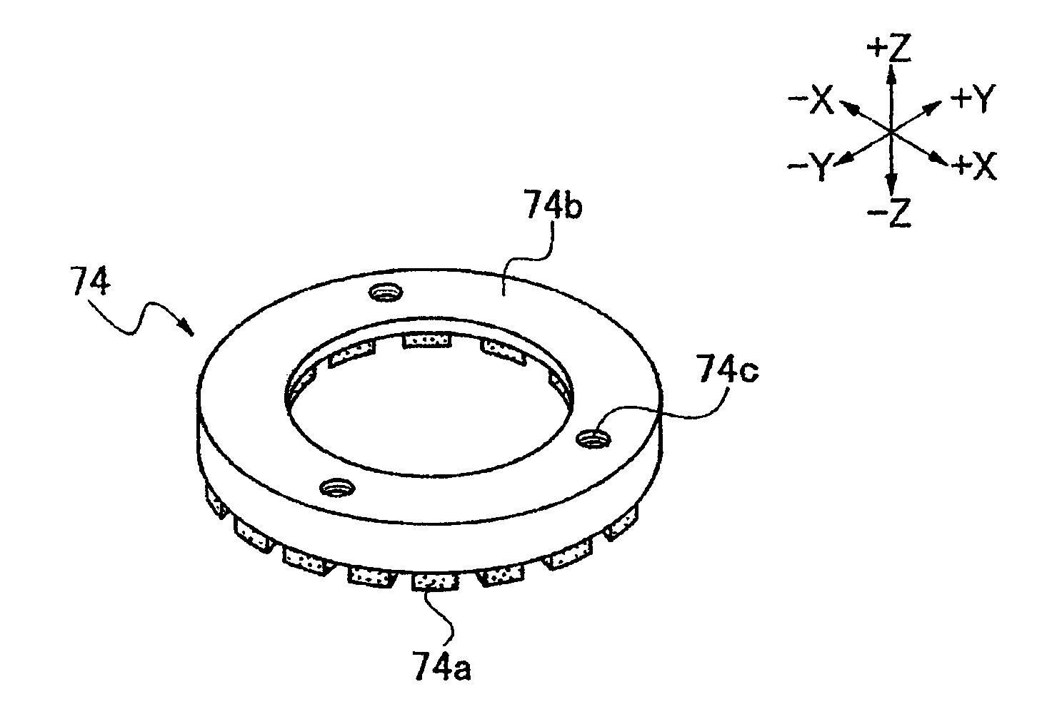
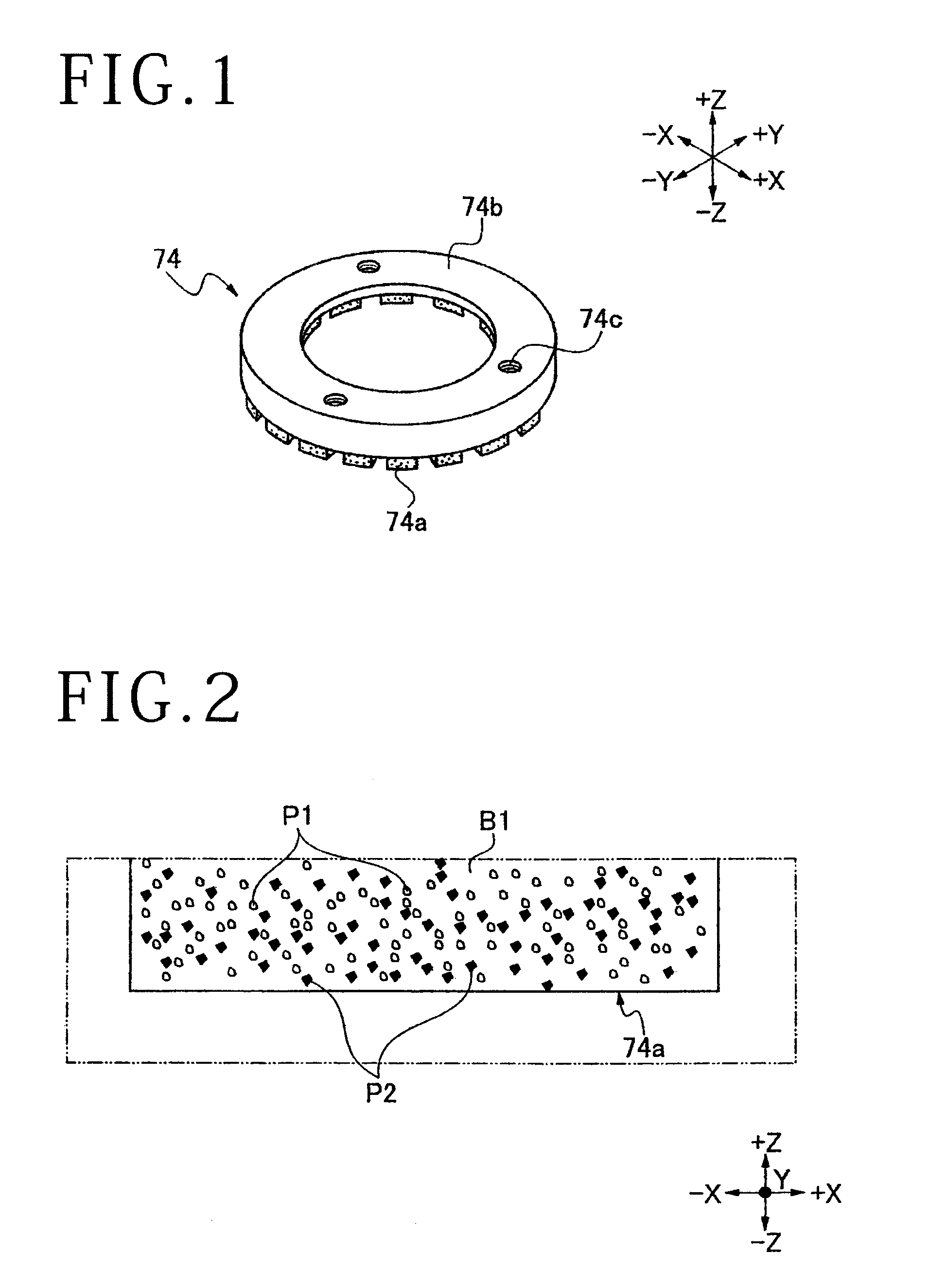
[0026]As shown in FIG. 1, a grinding wheel 74 includes an annular wheel base 74b and a plurality of grinding stones 74a, each substantially in the form of a rectangular parallelepiped, disposed in an annular pattern on and fixed to an outer circumferential portion of the bottom surface (lower free end) of the wheel base 74b. The wheel base 74b has screw holes 74c defined in the upper surface thereof. As shown in FIG. 2, each of the grinding stones 74a is made of a mixture of diamond abrasive grains P1 and titanium oxide (TiO2) particles P2, which serve as photocatalytic particles, that are held together by a phenolic resin binder B1 and molded to shape. The grinding stones 74a may be replaced with an integral annular grinding stone.

[0027]The grinding wheel 74 is manufactured, for example, as follows: First, phenolic resin by a weight ratio of 100, which serves as phenolic resin binder B1, is mixed with diamond abrasive grains P1, each having a diameter of about 10 μm, by a weight ra...


PUM


Abstract

Disclosed herein is a grinding wheel including an annular wheel base and a plurality of grinding stones fixed to an outer circumferential portion of the lower end of the annular wheel base. Each of the grinding stones is made of a mixture of abrasive grains and photocatalytic particles which are held together by a binder. The abrasive grains are diamond abrasive grains, and the photocatalytic particles are titanium oxide (TiO2) particles.

Description

BACKGROUND OF THE INVENTION[0001]1. Field of the Invention[0002]The present invention relates to a grinding wheel for grinding a wafer, a grinding apparatus having a grinding wheel, and a method of grinding a wafer.[0003]2. Description of the Related Art[0004]Wafers on which devices such as ICs, LSI circuits, LEDs, SAW devices, or the like have been separated by projected dicing lines and formed on their surfaces are ground on their reverse sides to a predetermined thickness by a grinding apparatus having a rotatable grinding wheel, and then divided by a dividing apparatus such as a dicing apparatus, a laser machining apparatus, or the like into individual devices for use in various electronic devices, etc.[0005]The grinding apparatus generally includes a chuck table for holding a wafer thereon, grinding means having a rotatable grinding wheel which includes an annular array of grinding stones for grinding the wafer held on the chuck table, grinding water supply means for supplying ...

Claims


Application Information

Patent Timeline
IPC IPC(8): B24D7/06B24B7/00
CPCB24B7/00B24D7/06B24B7/228B24D3/285B24D5/06H01L21/304B24B7/241
Inventor TAKENOUCHI, KENJI
Owner DISCO CORP
Why Eureka
Try Eureka