
Ball chair

a ball chair and structure technology, applied in the field of ball chairs, can solve the problems of screw damage, difficulty in assembling the ball chair, accidental or injury to the user, etc., and achieve the effect of quick and easy engagement, preventing the ball from being damaged, and increasing convenien

Active Publication Date: 2016-09-01
FAMOSA CORP
View PDF0 Cites 1 Cited by
  • Summary
  • Abstract
  • Description
  • Claims
  • Application Information

AI Technical Summary

Benefits of technology

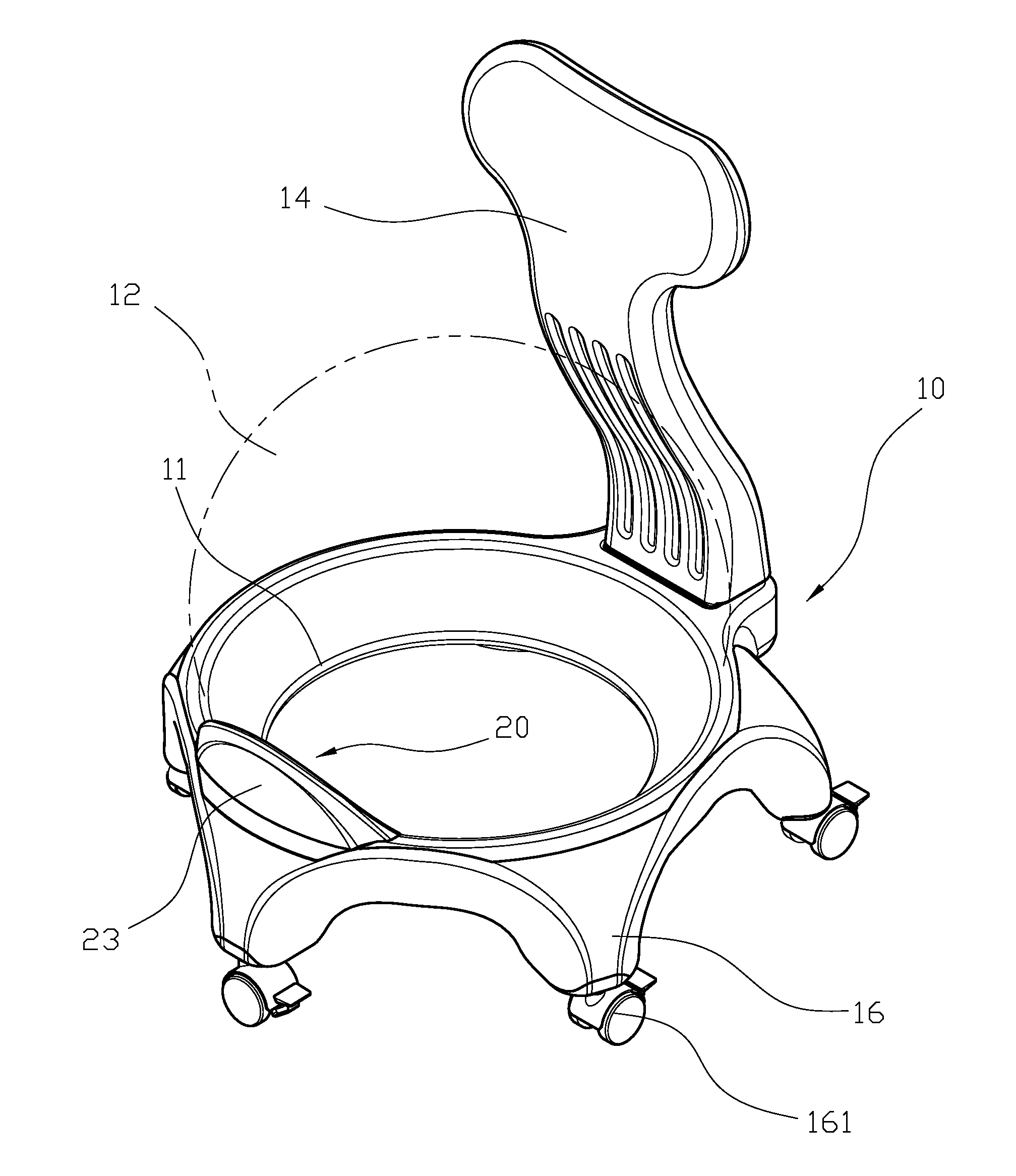
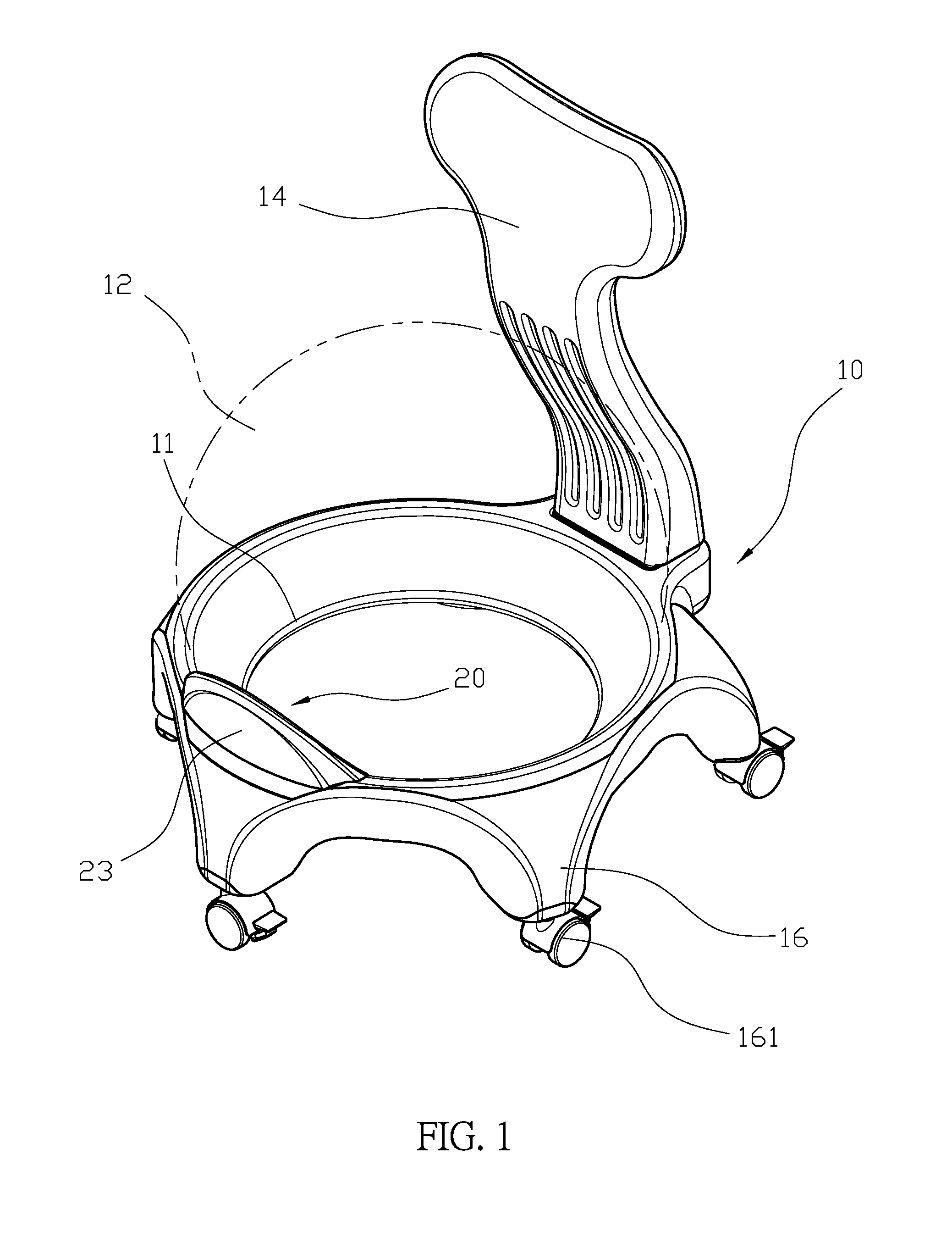
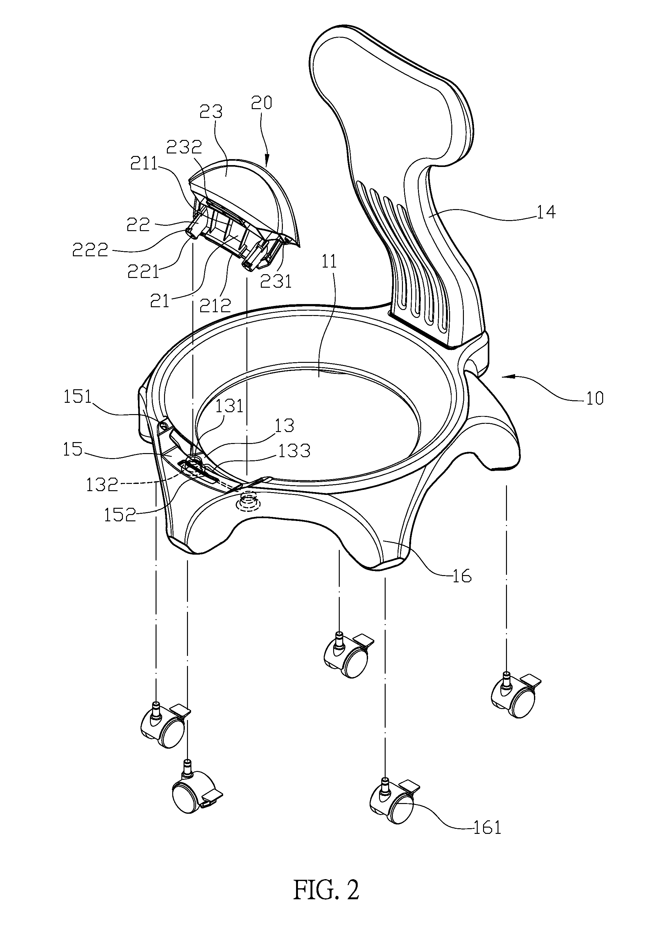
[0007]Comparing with conventional ball chairs, the present invention is advantageous because: (i) the connecting portion of the chair base is provided for the restricting unit to restrict the ball, and the restricting unit and the connecting portion can be quickly and easily engaged to increase the convenience during the assembling process and prevent the ball from being damaged; (ii) when the restricting unit is attached to the chair base, the arc board is attached and aligned with the inner wall of the receiving space, so when the ball is inserted into the receiving space, the ball can be smoothly attached to the inner wall of the receiving space and can be used to push the arc board of the restricting unit to restrict the restricting unit on the chair base to increase the stability of the ball on the chair base, and further increase the safety of the ball chair; and (iii) the restricting unit and the chair base are connected through engagement, so they can be disassembled into smaller pieces which can be easily transported and the transportation costs can be reduced.

Problems solved by technology

The conventional ball chair is disadvantageous because it may be unstable when the user is sitting thereon and the ball may even fall off the chair, which can cause accident or injury to the user.
Although the positioning unit 33 can be secured on the connecting portion 32, it is difficult for the user to assemble the ball chair.
Furthermore, the ball 34 may be damaged by the screw 331.
Moreover, referring to FIG. 8 for another conventional ball chair 40, which has a positioning unit 41 and the positioning unit 41 cannot be removed from the ball chair 40, so the size of the ball chair increases, which may increase the costs for transportation and increase the usage of the packaging materials.

Method used


Image

  • Ball chair
  • Ball chair
  • Ball chair

Examples


Embodiment Construction

[0016]The detailed description set forth below is intended as a description of the presently exemplary device provided in accordance with aspects of the present invention and is not intended to represent the only forms in which the present invention may be prepared or utilized. It is to be understood, rather, that the same or equivalent functions and components may be accomplished by different embodiments that are also intended to be encompassed within the spirit and scope of the invention.

[0017]Unless defined otherwise, all technical and scientific terms used herein have the same meaning as commonly understood to one of ordinary skill in the art to which this invention belongs. Although any methods, devices and materials similar or equivalent to those described can be used in the practice or testing of the invention, the exemplary methods, devices and materials are now described.

[0018]All publications mentioned are incorporated by reference for the purpose of describing and disclos...


PUM


Abstract

A ball chair may include a chair base and a restricting unit. The chair base has a circular receiving space to receive a ball and an inner portion of the receiving space has a connecting portion that has at least two through holes. The restricting unit has an arc board and a connecting post conjugating with the connecting portion. A restricting board extends from the arc board corresponding to the connecting recessed portion, and the restricting board is protruding from an upper portion of the receiving space. The connecting portion of the chair base is provided for the restricting unit to restrict the ball, and the restricting unit and the connecting portion can be quickly and easily engaged increase the convenience during the assembling process and prevent the ball from being damaged.

Description

FIELD OF THE INVENTION[0001]The present invention relates to a ball chair structure, and more particularly to a ball chair that can be quickly and easily assembled.BACKGROUND OF THE INVENTION[0002]A conventional ball chair is shown in FIGS. 6 and 7. The conventional ball chair is disadvantageous because it may be unstable when the user is sitting thereon and the ball may even fall off the chair, which can cause accident or injury to the user. Thus, the conventional ball chair has been modified to increase the stability of the ball. The modified ball chair may have a connecting portion 32 on top of the through hole 31 of the chair base 30 and a positioning unit 33 is disposed on the connecting portion 32 to further restrict the ball 34 to prevent the ball from falling off.[0003]However, conventional ball chair described above still has some problems: the connecting portion 32 has a plurality of through holes and the positioning unit 33 has a screw 331 corresponding to the connecting ...

Claims


Application Information

Patent Timeline
Patent Type & Authority Applications(United States)
IPC IPC(8): A47C3/00A47C7/00A47C7/02A47C4/02
CPCA47C3/00A47C7/02A47C7/006A47C4/02A47C9/002
Inventor CHIU, CIBER
Owner FAMOSA CORP
Learn More