
Impactor

a technology of impactors and implants, applied in the field of impactors, can solve problems such as not always easy to achieve, and achieve the effect of quick and easy engagement with implants

Active Publication Date: 2012-10-02
ENZTEC LTD
View PDF7 Cites 6 Cited by
  • Summary
  • Abstract
  • Description
  • Claims
  • Application Information

AI Technical Summary

Benefits of technology

[0008]An object of the present invention is the provision of an impactor which is capable of holding an implant in the correct orientation during impact, but which can be quickly and easily engaged with an implant.

Problems solved by technology

However, known designs of impactor typically require very precise, positive adjustment to engage the impactor correctly with the implant, and this is not always easy to achieve under surgical conditions.

Method used


Image

  • Impactor
  • Impactor
  • Impactor

Examples


Embodiment Construction

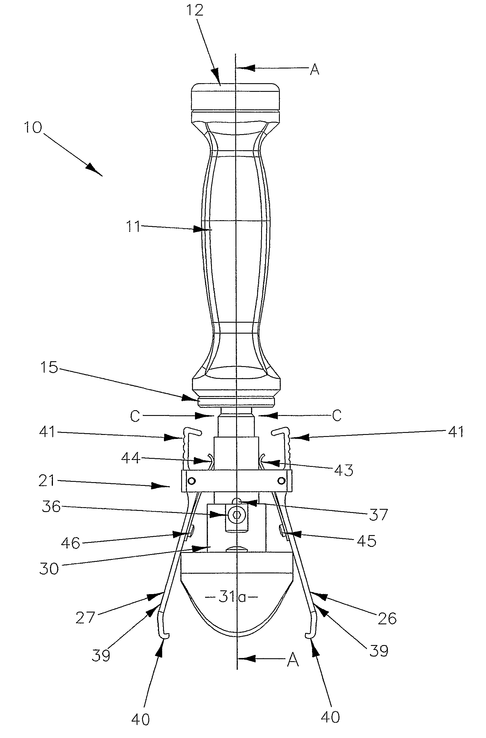
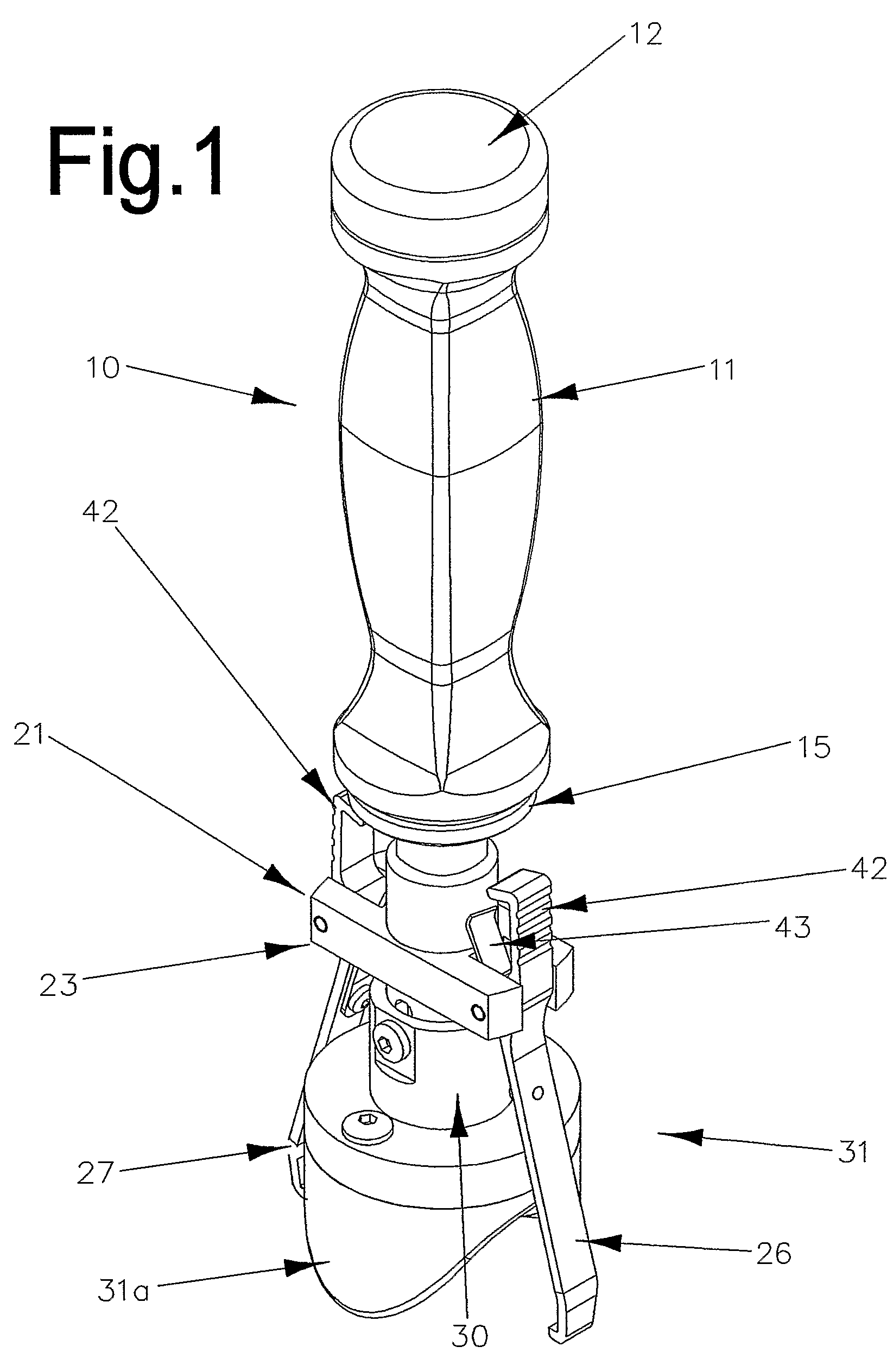
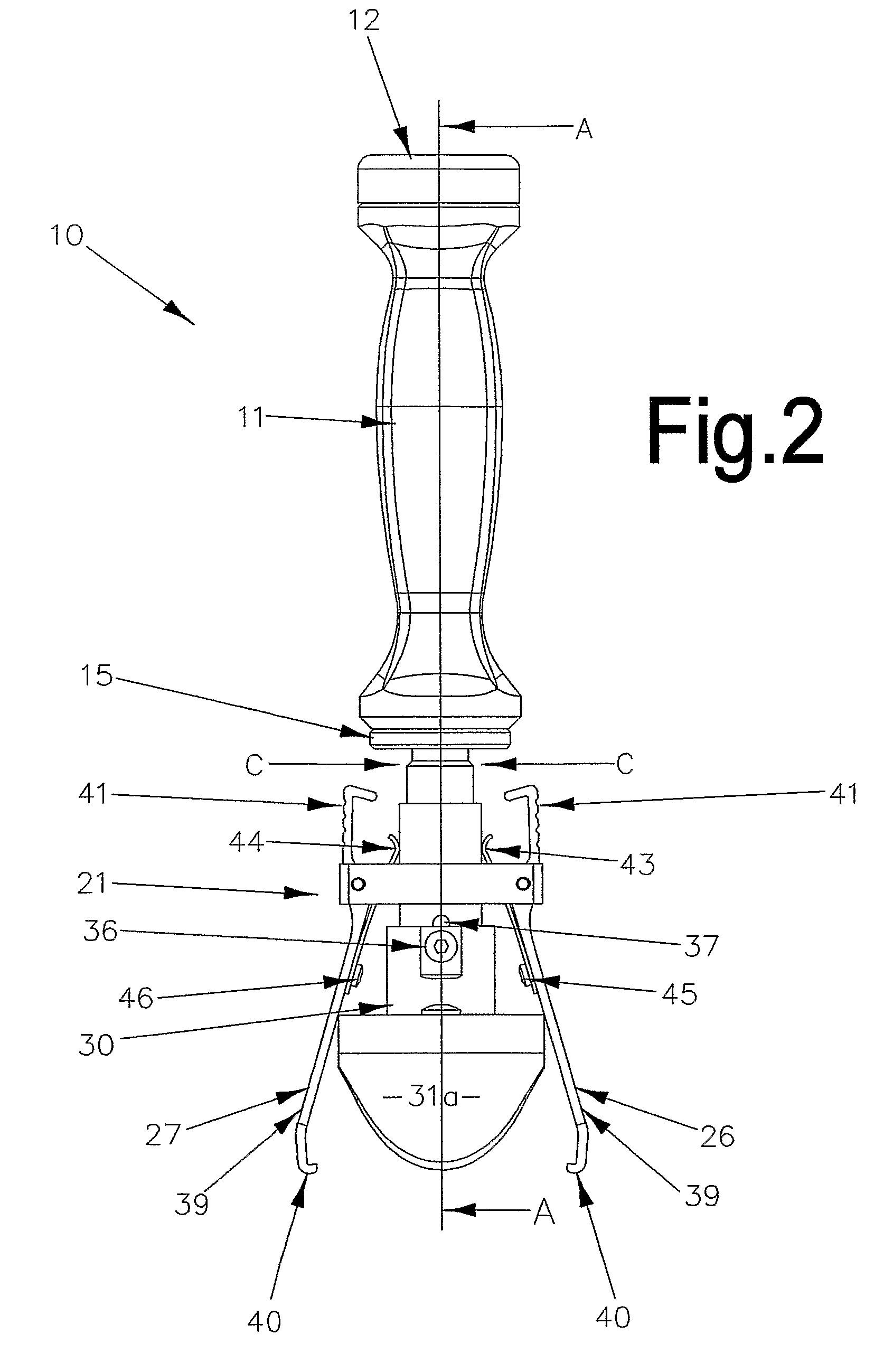
[0038]Referring to the drawings, an impactor 10 in accordance with the present invention includes an impaction means in the form of a handle 11 which carries an anvil 12 at one end. The anvil 12 may be formed integrally with the top of the handle. The handle 11 is connected to an impaction shoe 31 by connection means which include shafts 13 and 16 and housing 21.

[0039]The other end of the handle 11 is mounted upon a first shaft 13 which extends along part of the longitudinal axis of the handle 11. The shaft 13 is formed integrally with an impact plate 15 in contact with the other end of the handle. The side of the impact plate 15 opposite to the shaft 13 is formed integrally with a second shaft 16 coaxial with the shaft 13. The portion 17 of the second shaft 16 adjacent to the impact plate 15 is externally screw threaded; the remaining portion of the shaft 16 is of reduced diameter and formed as a smooth cylinder 18. A coil spring 19 is mounted upon the cylinder 18.

[0040]The portion...


PUM


Abstract

An impactor for positioning and holding a surgical or veterinary prosthetic implant while it is being driven into position, said impactor including:(a) an impaction means;(b) an impaction shoe which is configured to receive and support a prosthetic implant in a predetermined position;(c) connection means which connect the impaction means to the impaction shoe and are configured to transmit an impact from the impaction means to the impaction shoe;(d) arms configured to engage an implant supported upon the impaction shoe;(e) said arms being biased into engagement with said implant, but movable against the bias out of engagement with the implant;(f) said connection means being adjustable between a first setting at which the impaction shoe is spring-loaded so as to bias an implant supported upon the impaction shoe into engagement with said arms but at which the impaction shoe can slide relative to said arms, against said spring bias; and a second setting at which both the impaction shoe and the arms are rigidly engaged with an implant supported upon the impaction shoe, to hold the implant in a predetermined position and orientation relative to the impaction means.

Description

BACKGROUND OF THE INVENTION[0001](1) Field of the Invention[0002]The present invention relates to an impactor for positioning and holding surgical or veterinary prosthetic implants while they are being driven into position. The present invention has been designed specifically for femoral knee implants, and therefore will be described with particular reference to that application. However, it will be appreciated that the impactor of the present invention could be adapted for use with any surgical or veterinary prosthetic implant which requires driving into position.[0003](2) Description of Related Art[0004]Any discussion of the prior art is not an admission that such prior art is widely known or forms part of the common general knowledge in the field.[0005]Ideally, an impactor needs to be capable of holding a range of different sizes of implants, and must also be capable of holding each implant in the correct orientation during impact.[0006]Some of the known impactors are designed sp...

Claims


Application Information

Patent Timeline
Patent Type & Authority Patents(United States)
IPC IPC(8): A61B17/58
CPCA61B17/92A61F2/461A61F2002/4628A61F2002/4681A61F2002/30565
Inventor MCMILLAN, IAIN ALEXANDERMORRISON, PAUL JOHN
Owner ENZTEC LTD
Learn More