Dynamic means for correcting for load imbalance and harmonic distortion

a dynamic means and harmonic distortion technology, applied in the field of switching circuits, can solve the problems of no effective means or methods for correcting imbalance or harmonic distortion in industrial and commercial settings, and the failure to turn the switch exactly at the zero crossing of the line voltage, etc., to achieve the effect of facilitating the safe transfer of energy

Active Publication Date: 2016-08-25
POWERMETRICS INT
View PDF0 Cites 0 Cited by
  • Summary
  • Abstract
  • Description
  • Claims
  • Application Information

AI Technical Summary

Benefits of technology

[0009]The present invention provides a novel means for measuring the negative energy within a closed AC electronic system that will correct for load imbalance and harmonic distortion. As part of this novel means the system itself can designate master slave relationships within the closed system to facilitate the safe transfer of energy from a source to a load while overcoming the deficiencies of conventional circuit protection and correction devices.
[0012]Among features and benefits provided by the various embodiments, this ability to synchronize the zero crossing of the voltage and the current in the second quadrant of the AC waveform the current delivery to the load provides substantially improved imbalance correction of AC voltage.

Problems solved by technology

Consequently, it is impossible to turn the switch on exactly at the zero crossing of the line voltage.
Currently, there are no effective means or methods for correcting for imbalance or harmonic distortion within industrial and commercial settings.
Under these two methods there is a problem to overcome.
Under these applications both switches and capacitors are damaged and frequent replacements are the common practice.
The costs for generating as well as for electricity have risen as demand has increased.

Method used


Image

  • Dynamic means for correcting for load imbalance and harmonic distortion
  • Dynamic means for correcting for load imbalance and harmonic distortion
  • Dynamic means for correcting for load imbalance and harmonic distortion

Examples


Embodiment Construction

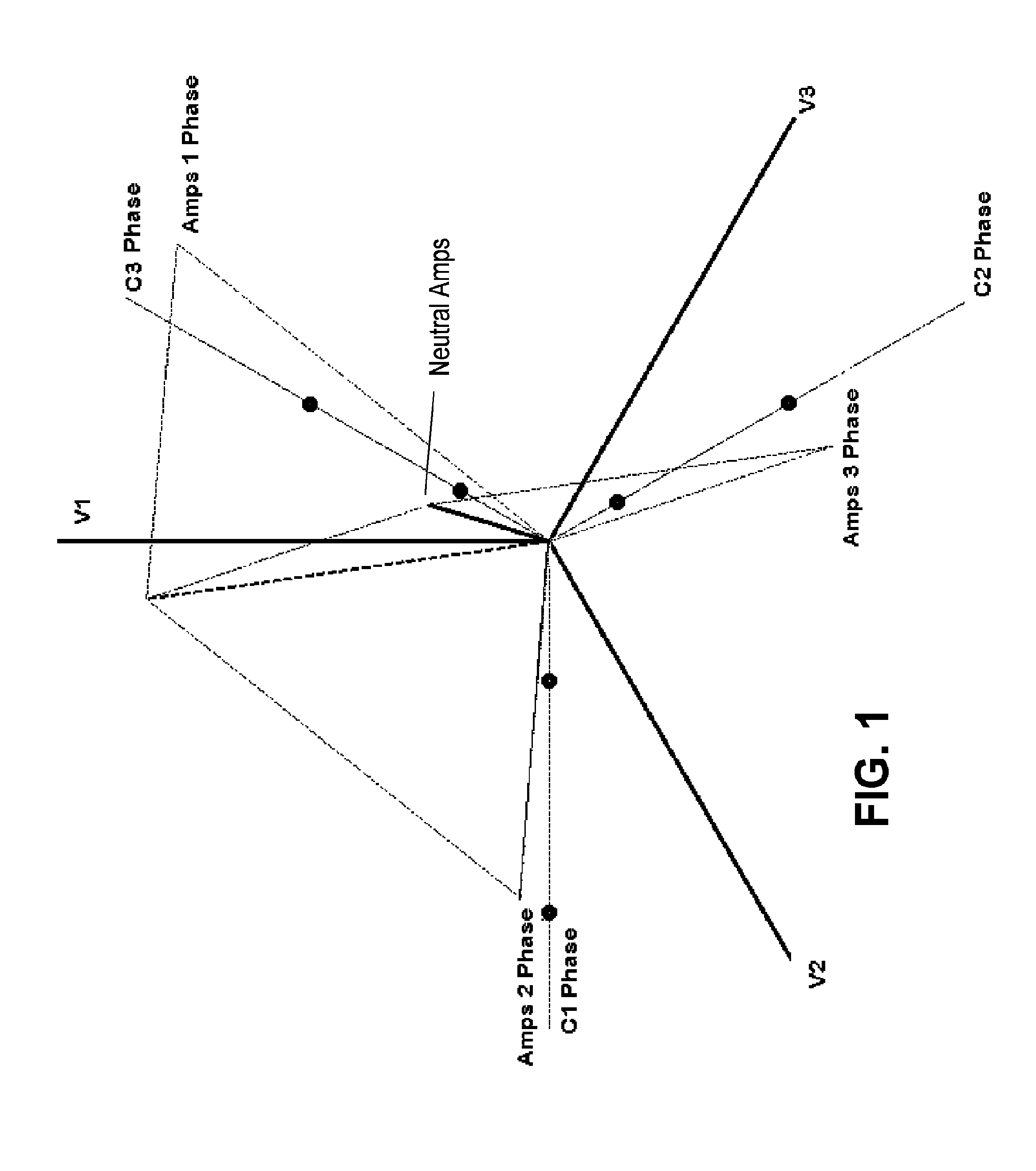
[0024]FIG. 1 is a graphical depiction, which shows a phase diagram of the statures of the panel before any correction is made by implementing the current invention. This figure specifically shows the relative phase relationship between all voltages and currents in a typical phase 3 system. The solid red line represents imbalance current in neutral line. It is produced by vector sum of all currents involved. The red dots of capacitor phase lines indicate the maximum and minimum amount of capacitance that is allowed for the panel. These limits will assure the stability of the system so it does not create harmonics and will produce minimum acceptable phase correction.

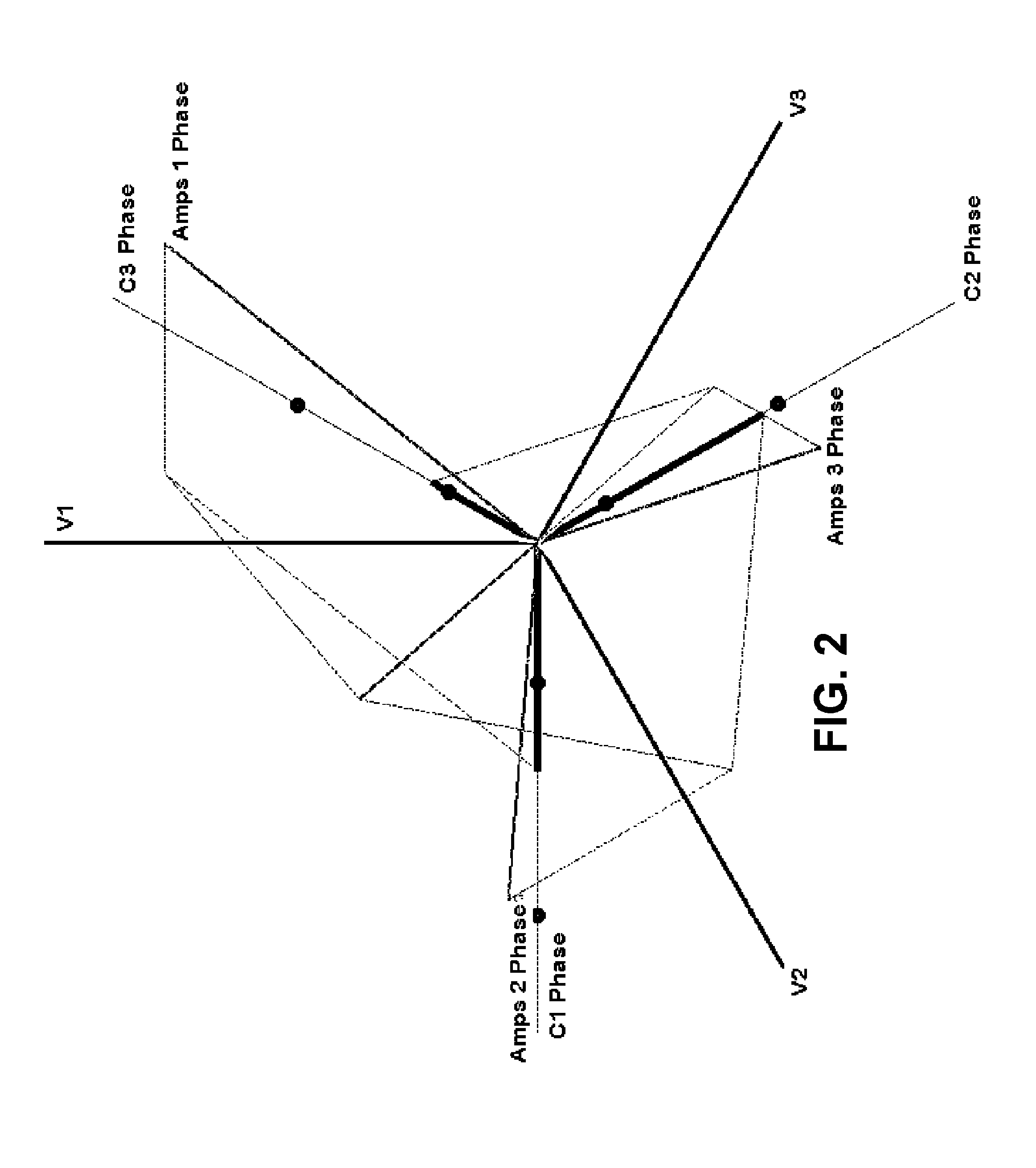
[0025]FIG. 2 is a graphical depiction, which shows the correction achieved by implementing the current invention. The thick purple lines indicate the amount of capacitance applied to each phase. The red line indicating the neutral current in FIG. 1 has disappeared indicating there is no more current being wasted in neutral...


PUM


Abstract

A method and apparatus are directed to a dynamic means for correcting imbalance and harmonic distortion in an electrical system. In one embodiment, the device includes an imbalance and harmonics measurement module configured to measure power parameters for determining imbalance and harmonics within the electrical three-phase system. Within this system a series of capacitors are configured to respond to measured demands reported and designated to correct for imbalance and harmonics distortion. The device is networked among various source load controllers are responsible for designating master and slave relationships within the closed system.

Description

[0001]This is a continuation of application Ser. No. 13 / 763,624 filed Feb. 9, 2013. application Ser. No. 13 / 763,624 is hereby incorporated by reference in its entirety.FIELD OF INVENTION[0002]This invention relates to switching circuits. More specifically, effectively switching on and off a capacitor or capacitor bank within a closed system in response to measured load imbalance and harmonic distortion that utilizes master slave relationships with a closed electronic system. This invention is applicable to arc welding, magnetizing materials, and switching capacitors no list only three applications via a novel means.BACKGROUND[0003]In a typical power line capacitor switching system application, electrical parameters of the power drawn is measured using integrated circuits, the parameter also indicating the reactive power by a load and then communicating via a switching device to a capacitor bank which thereby attempts to match the load of a power line at an designated signal value or...

Claims


Application Information

Patent Timeline
Patent Type & Authority Applications(United States)
IPC IPC(8): H02J3/26H02J3/28H02M1/08H02M5/293H02M1/12H02M1/42H05B44/00
CPCH05B33/0815H02J3/26H02J3/28H05B33/0809Y02E40/50H02M1/12H02M1/42H02M5/293H02M2001/0009H02M1/08H05B45/3725H02M1/0009
Inventor PISHDADIAN, HAMID
Owner POWERMETRICS INT
Why Eureka
Try Eureka