
Electrostatic discharge protection device

a protection device and electrostatic discharge technology, applied in emergency protective circuit arrangements, emergency protective arrangements for limiting excess voltage/current, electric devices, etc., can solve the problem of frequently mis-triggered devices

Inactive Publication Date: 2016-08-18
MACRONIX INT CO LTD
View PDF4 Cites 13 Cited by
  • Summary
  • Abstract
  • Description
  • Claims
  • Application Information

AI Technical Summary

Benefits of technology

The invention is about an electrostatic discharge (ESD) protection device that uses multiple voltage drop elements connected in series to prevent false triggering. This device ensures that the voltage from the first line is greater than the activation voltage to avoid unnecessary damage to electronic components. The driving circuit controls the clamping circuit based on the control signal from the node. As a result, this ESD protection device prevents false triggering and provides efficient protection against ESD damage.

Problems solved by technology

Nevertheless, during the normal operation of the integrated circuit, the existing ESD protection device is frequently mis-triggered by noise, and the integrated circuit is influenced by the ESD protection device.
Hence, how to design an ESD protection device capable of avoiding false triggering has become a challenge to various manufacturers.

Method used


Image

  • Electrostatic discharge protection device
  • Electrostatic discharge protection device
  • Electrostatic discharge protection device

Examples


Embodiment Construction

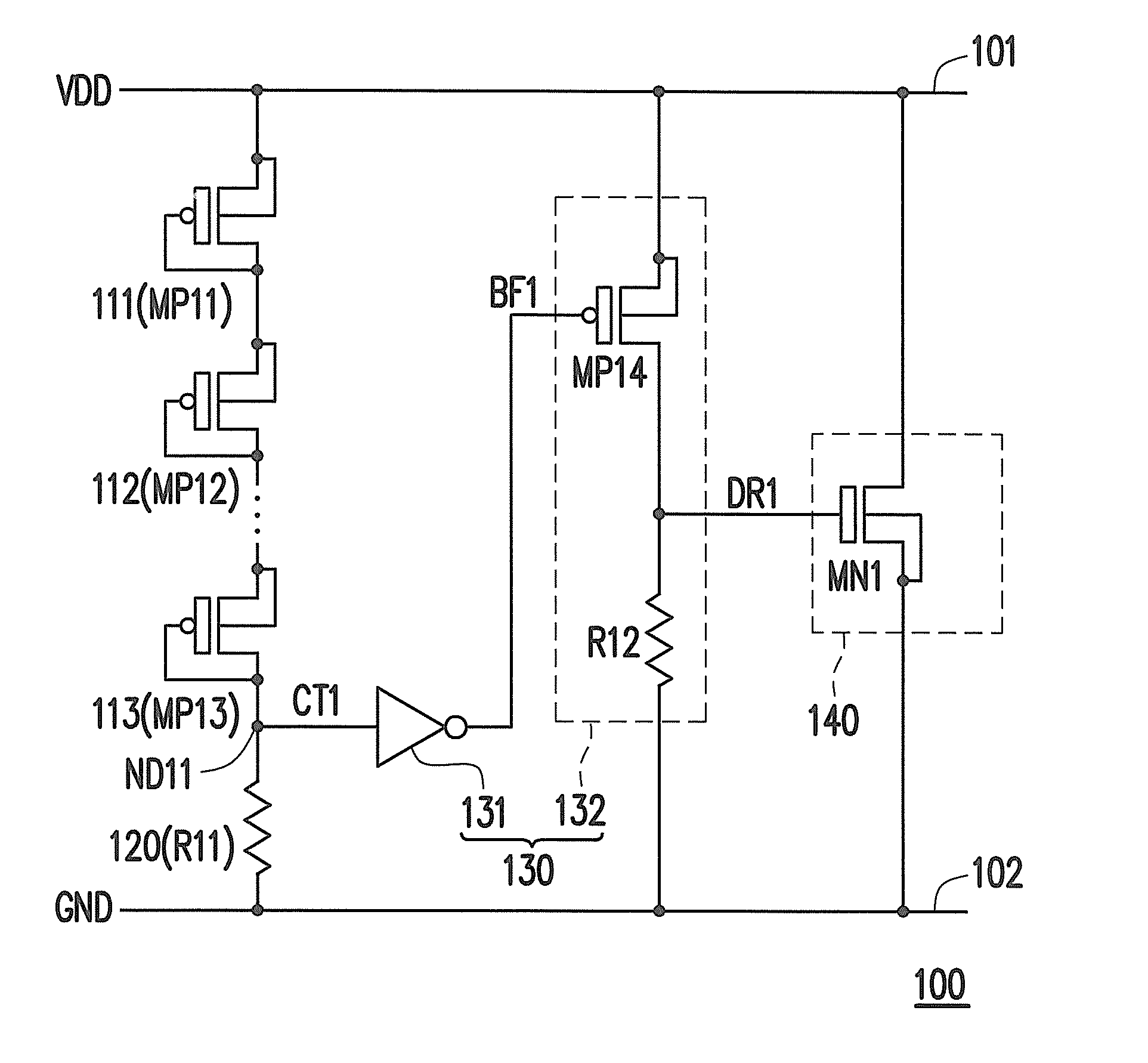
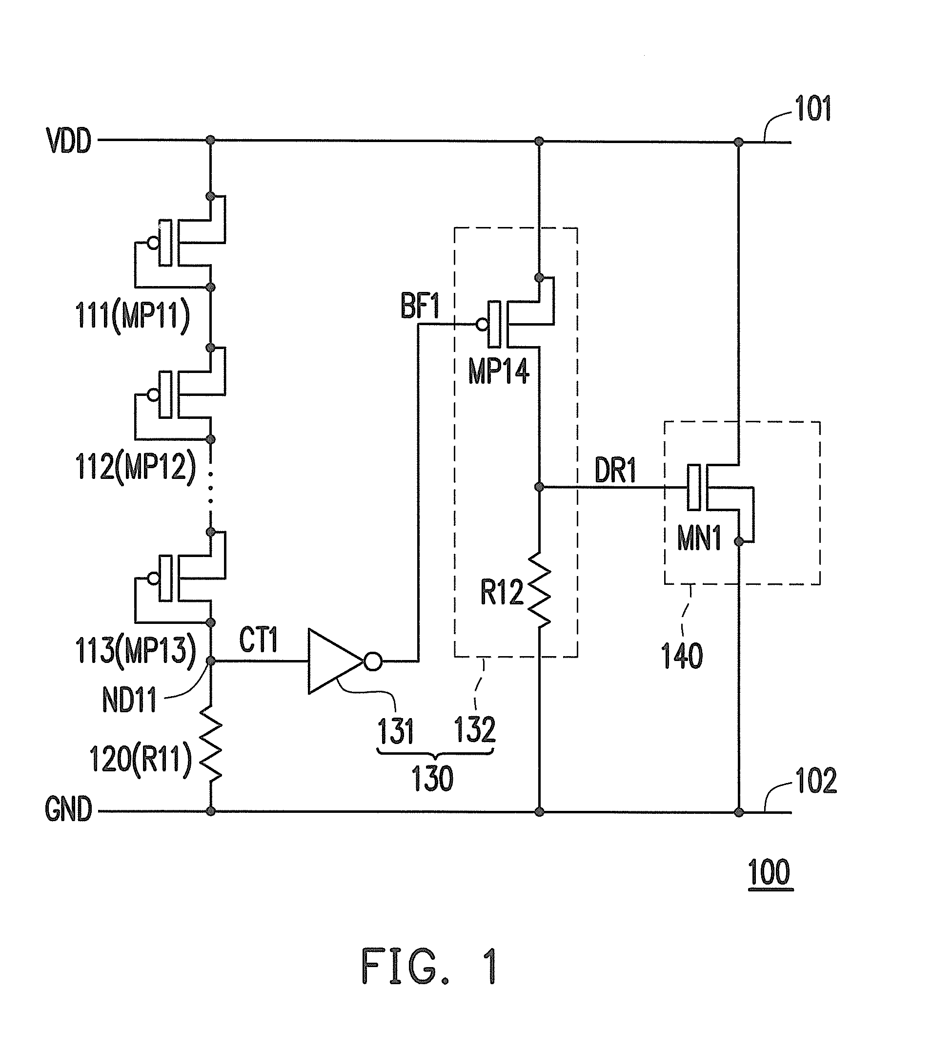
[0015]FIG. 1 is a schematic view illustrating an electrostatic discharge (ESD) protection device according to an embodiment of the invention. With reference to FIG. 1, the ESD projection device 100 includes a plurality of voltage drop elements 111 to 113, an impedance element 120, a driving circuit 130, and a clamping circuit 140. The voltage drop elements 111 to 113 are connected in series between a first line 101 and a node ND11. The impedance element 120 is electrically connected between the node ND11 and a second line 102. The driving circuit 130 is electrically connected to the node ND11, and the clamping circuit 140 is electrically connected to the driving circuit 130.

[0016]The impedance element 120 may be a resistor R11, for instance. Besides, in response to the signal from the first line 101, the voltage drop elements 111 to 113 determine whether to conduct the first line 101 to the node ND11. For instance, each of the voltage drop elements may be constituted by a PMOS trans...


PUM


Abstract

An electrostatic discharge protection device that includes a plurality of voltage drop elements, an impedance element, a driving circuit, and a clamping circuit is provided. The voltage drop elements are electrically connected in series between a first line and a node, and the voltage drop elements are configured to define an activating voltage. If a signal from the first line is greater than the activating voltage, the voltage drop elements conduct the first line to the node in response to the signal from the first line. The impedance element is electrically connected between the node and a second line. The driving circuit amplifies a control signal from the node and accordingly generates a driving signal. The clamping circuit determines whether to generate a discharging path between the first line and the second line according to the driving signal.

Description

FIELD OF THE INVENTION[0001]The invention relates to a protection device; more particularly, the invention relates to an electrostatic discharge (ESD) protection device.DESCRIPTION OF RELATED ART[0002]Integrated circuits are often equipped with electrostatic discharge (ESD) protection devices to prevent damages caused by ESD. Nevertheless, during the normal operation of the integrated circuit, the existing ESD protection device is frequently mis-triggered by noise, and the integrated circuit is influenced by the ESD protection device. Hence, how to design an ESD protection device capable of avoiding false triggering has become a challenge to various manufacturers.SUMMARY OF THE INVENTION[0003]The invention is directed to an electrostatic discharge (ESD) protection device, in which plural voltage drop elements are connected in series so as to avoid false triggering of the ESD protection device.[0004]In an embodiment of the invention, an ESD protection device includes a plurality of v...

Claims


Application Information

Patent Timeline
IPC IPC(8): H02H9/04
CPCH02H9/04H02H9/046
Inventor WANG, SHIH-YUHE, CHIEH-WEICHANG, YAO-WENLU, TAO-CHENG
Owner MACRONIX INT CO LTD
Learn More