
Detergent delivery methods and systems for turbine engines

a technology of detergent and turbine engine, which is applied in the direction of machines/engines, mechanical equipment, transportation and packaging, etc., can solve the problems of reducing the cooling efficiency of the circuit, affecting the efficiency of the engine, so as to achieve the effect of substantial disassembly

Active Publication Date: 2016-08-18
GENERAL ELECTRIC CO
View PDF4 Cites 11 Cited by
  • Summary
  • Abstract
  • Description
  • Claims
  • Application Information

AI Technical Summary

Benefits of technology

The technical effect of the patent is that impingement internal cooling circuits of turbine engines tend to become blocked with particulate matter, which reduces the cooling efficiency of the circuits and causes the components to operate at higher temperatures. This can lead to reduced life and increased operating temperatures, as well as potential corrosion of components. The patent proposes a solution to prevent and mitigate the negative effects of particulate matter on turbine engines.

Problems solved by technology

Unfortunately, impingement internal cooling circuits of turbine engines tend to become partially or completely blocked with particulate matter that reduces the cooling efficiency of the circuits.
For example, particulate matter may enter a turbine engine during service or during use, such as during environmental events such as dust storms.
In addition to blocking or clogging the cooling circuits, the particulate matter may also become deposited on cooled components and create an insulating layer between the surface of the component and the cooling medium of the cooling circuits.
The reduced cooling efficiency created by the at least partially blocked cooling circuits and the insulating layers on the cooled components can increase the operating temperature and reduce the life of the components.
In addition, the particulate matter that is entrained in the air that enters the turbine engine and travels within the cooling circuits can contain sulphur-containing species which can corrode components of the turbine.
Unfortunately, internal cooling passages that are designed to cool one or more components of gas turbine engines are typically either not cleaned or cleaned through expensive, time consuming, labor intensive and / or ineffective means.

Method used


Image

  • Detergent delivery methods and systems for turbine engines
  • Detergent delivery methods and systems for turbine engines
  • Detergent delivery methods and systems for turbine engines

Examples


example 1

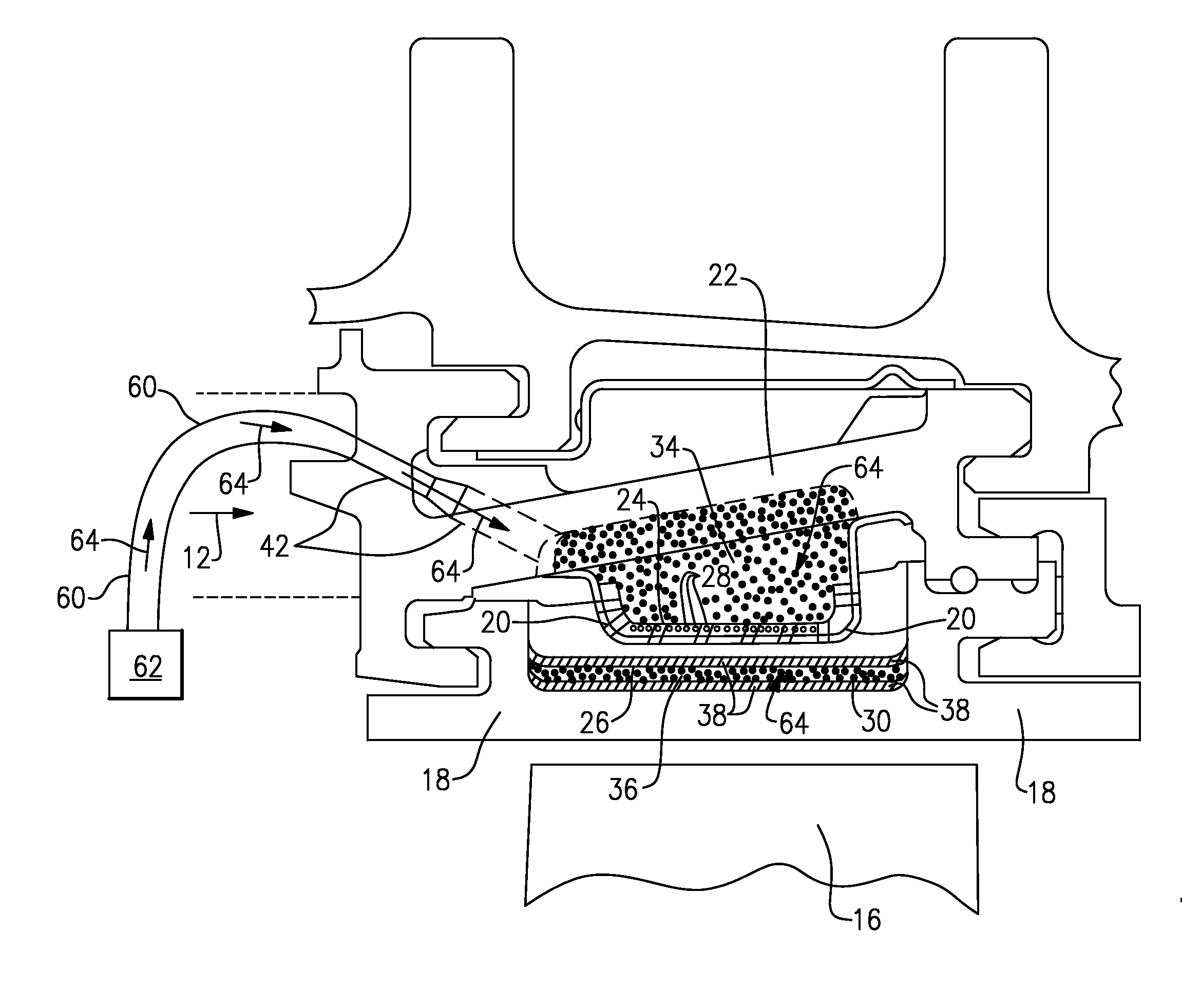
[0061]Tests of the delivery methods and system of the present disclosure were performed, in part, to analyze the effect of detergent flow rate on detergent shroud wetting and, ultimately, shroud cleaning. The flow through the baffle was also analyzed tested to ensure sufficient pressure of the impingement fluid through the apertures in the baffle plate at the front side of the baffle plate, so that each jet in the arrangement was essentially normal to the surface of the shroud for all positions around the full circumference of the circumferentially arranged shroud assembly in the engine.

[0062]The velocity of the impingement fluid through the shroud hanger apertures was about 1.3 m / s, and the velocity of the impingement fluid through the baffle apertures was about 0.4 m / s. In order to assess flow through the baffle plate apertures and the impingement of the detergent jets on the back side of the shroud, testing was performed with the shroud removed from the shroud hanger.

[0063]Wettin...

example 2

[0065]Tests were also performed to assess the cleaning effectiveness of the delivery methods and system of the present disclosure on an actual aircraft engine assembly.

[0066]A set of shrouds was removed from a wide-body aircraft engine that had operated for about 1000 cycles in environmental conditions that contained a relatively high concentration of airborne particulate, such as PM10 values of greater than about 80 micro grams per cubic meter, for example. The shrouds were then photographed, and assessed / measured for the degree of degradation, including flow path condition, cooling hole condition / performance, and the degree of particulate matter on the back side or impingement cooled surface of the shrouds. The shrouds were then re-assembled into the same engine position / configuration and the whole shroud assembly in the circumferential shroud hanger assembly was then subjected to a cleaning sequence of steam, detergent, and water, in order to test removal of the particulate matte...


PUM


Abstract

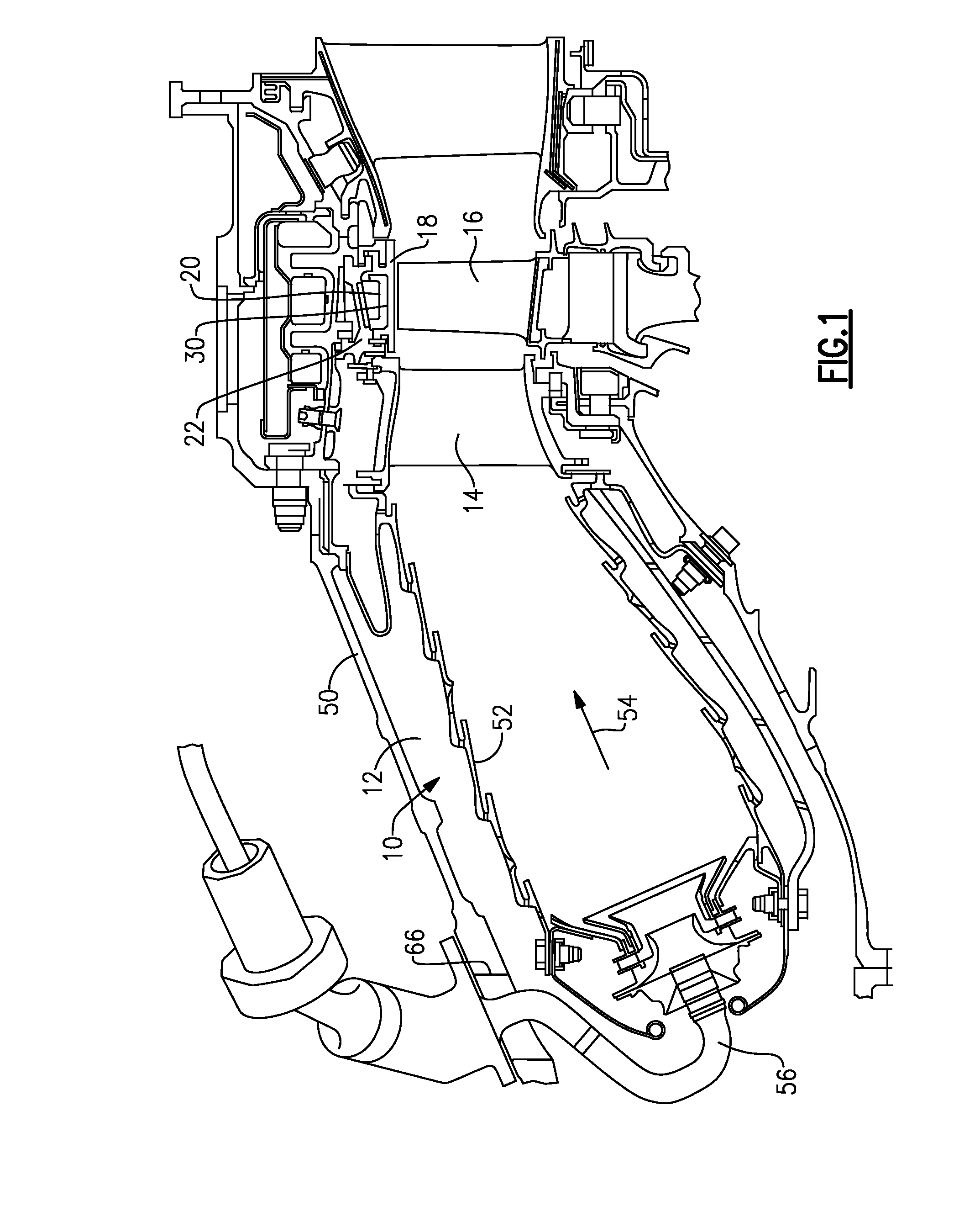
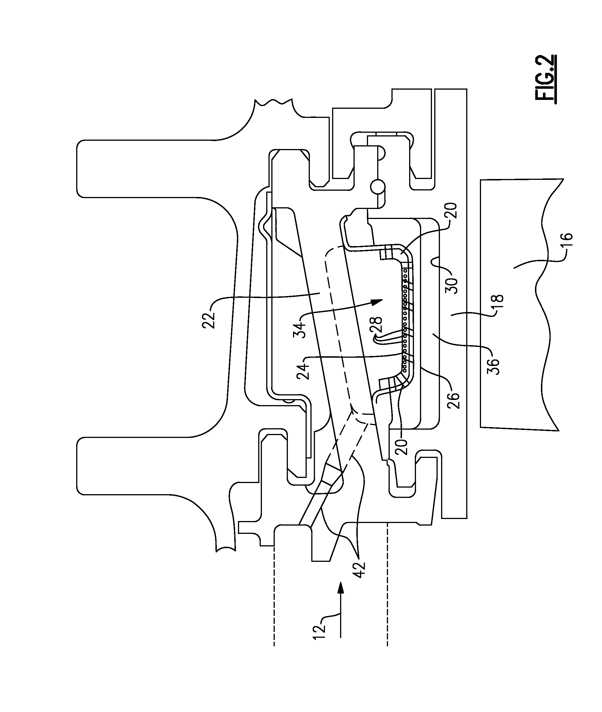
Methods and systems for in situ cleaning of internal cooling circuits of a turbine engine with detergent that provide cleaning a turbine engine that includes circumferentially arranged internal impingement cooling circuits that each include a baffle plate configured to air cool a respective surface or component of the turbine engine. Detergent is introduced through the outer wall and proximate to a back side of a baffle plate such that the detergent passes through at least aperture in the baffle plate and acts at least upon the surface or component that the baffle plate is configured to cool. The detergent may also act on the front side of the baffle plate that is proximate to the surface or component.

Description

[0001]The present application relates generally to methods and system for internal cleaning of turbine engines, and more particularly to methods and system of cleaning internal cooling circuits of turbine engines with detergent.[0002]Turbines, such as gas turbine engines, typically include internal cooling passages that are designed to impingement cool one or more components during use. For example, the high pressure section of a gas turbine engine typically includes numerous circumferentially-arranged impingement internal cooling circuits that allow for higher temperatures in the turbine. Unfortunately, impingement internal cooling circuits of turbine engines tend to become partially or completely blocked with particulate matter that reduces the cooling efficiency of the circuits. For example, particulate matter may enter a turbine engine during service or during use, such as during environmental events such as dust storms. The particulate matter may be fine scale (e.g., less than ...

Claims


Application Information

Patent Timeline
Patent Type & Authority Applications(United States)
IPC IPC(8): B64F5/00F01D25/00B08B9/032F01D25/12
CPCB08B9/032B64F5/0018F01D25/002F05D2220/323F05D2260/221F01D25/12F05D2220/32B64F5/30
Inventor BEWLAY, BERNARD PATRICKKULKARNI, AMBARISH JAYANTTIBBETTS, NICOLE JESSICAELLIS, BRIAN MICHAELBUENO, MANUEL K.REYES, EVERBATES, NOELKALB, BRIAN
Owner GENERAL ELECTRIC CO
Learn More