
Rifle end plate sling adapter and method

a technology of end plate and adapter, which is applied in the field of sling adapters, can solve the problems of additional work, skill, and installation of the adapter, and achieve the effect of maintaining the grip on the rifle over time and extensive disassembly

Active Publication Date: 2012-11-20
SAFARILAND
View PDF13 Cites 12 Cited by
  • Summary
  • Abstract
  • Description
  • Claims
  • Application Information

AI Technical Summary

Benefits of technology

[0010]Advantageously, the end plate sling adapter has attachment openings for use by both right-handed and left-handed operators, does not require extensive disassembly to install, and maintains its grip on a rifle over time. In addition, the end plate sling adapter of the present invention can be constructed from sturdy, relatively inexpensive, plastic materials, and can be used to provide an attachment point for a single-point rifle sling.

Problems solved by technology

One disadvantage of these adapter designs, however, is that over time the adapter can become worn and lose its secure grip on the rifle.
This causes the adapter to inadvertently slip down the receiver extension, shifting the anchor point of the single-point rifle sling.
A disadvantage of these adapter designs is that additional work, and perhaps skill, is required to install the adapter.
Although such materials provide for sturdy construction, such materials can also add expense to the manufacture of these adapters.

Method used


Image

  • Rifle end plate sling adapter and method
  • Rifle end plate sling adapter and method
  • Rifle end plate sling adapter and method

Examples


Embodiment Construction

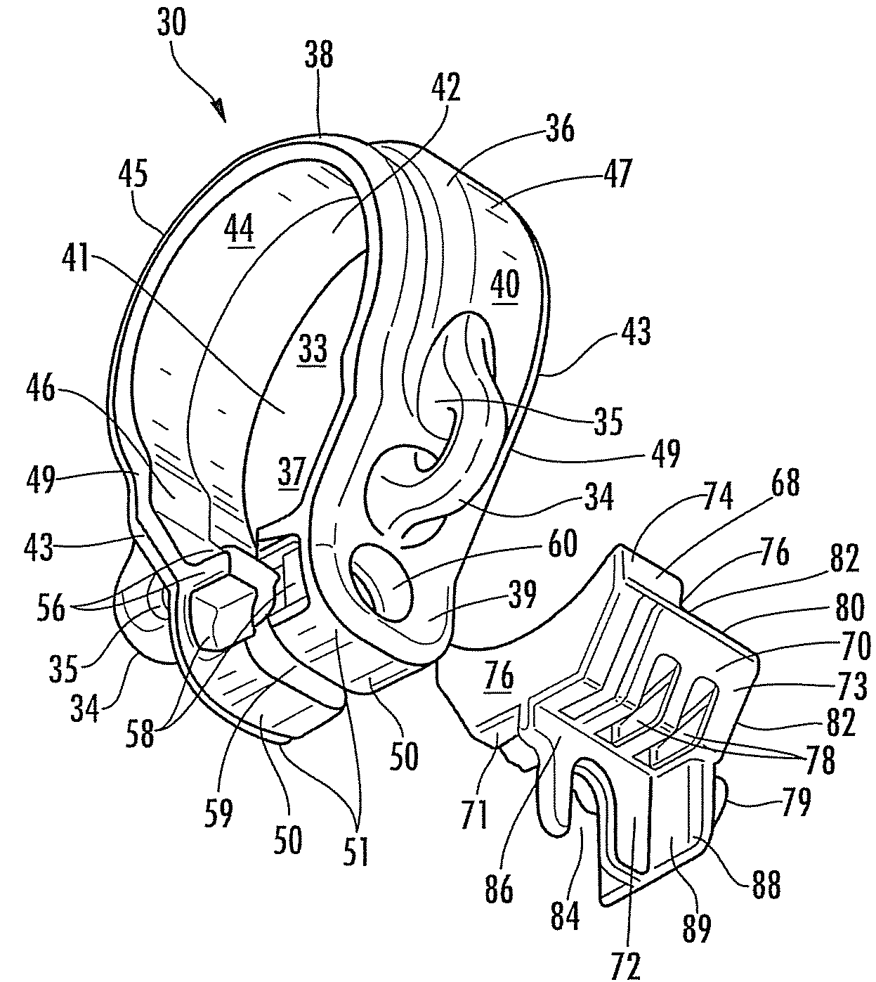
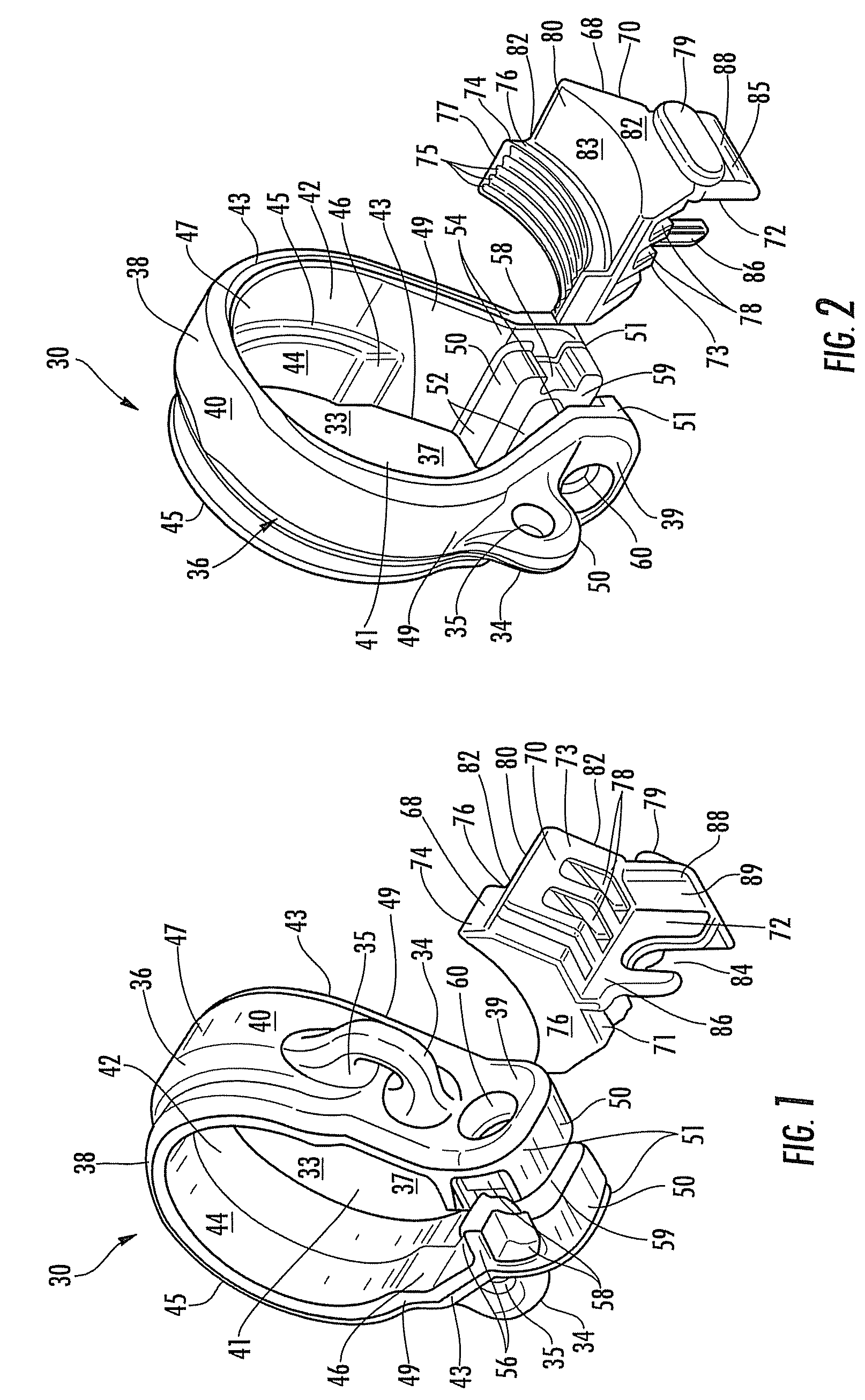
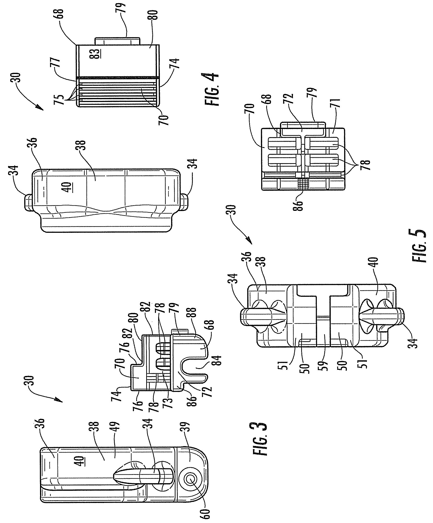
[0030]Embodying the principles of the present invention is an end plate sling adapter, a preferred embodiment of which is depicted in FIGS. 1-18 and designated generally by reference numeral 30. The end plate sling adapter 30 is shown in several of the FIGS. together with a rifle, designated generally by reference numeral 90.

[0031]The end plate sling adapter 30 is primarily constructed of a sturdy, plastic material, such as nylon. The sling adapter 30 is configured to slide over a receiver extension 93 of a buttstock assembly 91 of the rifle 90 and to be firmly secured to the receiver extension 93, as will be explained more fully herebelow. Attachment ears 34 provide attachment points for securing a harness to the sling adapter 30, as also explained more fully herebelow.

[0032]Referring now to FIGS. 1-5, the end plate sling adapter 30 includes a sling adapter clamp 36. The sling adapter clamp 36 comprises a collar 38 and a spaced pair of opposing fastener housings 50 (see FIGS. 1, 2,...


PUM

PropertyMeasurementUnit
widthaaaaaaaaaa
diameteraaaaaaaaaa
elliptical shapeaaaaaaaaaa

Abstract

End plate sling adapter securable to a rifle for a sling, includes a fastener element, sling adapter clamp and locking insert. Sling adapter clamp has a collar defining a central opening extending therethrough, and a pair of fastener housings arranged at respective ends of the collar defining a gap therebetween. Each housing receives a fastener therein such that the fastener extends across the gap and is adjustable to reduce its width. Locking insert has an upper portion with a threaded cradle accommodated within central opening and meshing with a threaded portion of a rifle buttstock receiver extension, and a lower portion extending into the gap.

Description

CROSS-REFERENCE TO RELATED APPLICATION[0001]This application claims the benefit of U.S. Provisional Application Ser. No. 61 / 203,795, filed on Dec. 29, 2008, the contents of which application are hereby incorporated by reference in their entirety.FIELD OF THE INVENTION[0002]The present invention relates generally to sling adapters to which are attached slings for carrying weapons.BACKGROUND[0003]A rifle sling is an important accessory that allows the operator of a rifle to keep both hands free while carrying the rifle. A number of sling designs exist. Three common sling designs are the single-point, two-point, and three-point slings. The number of points referenced in each design description refers to the number of points at which the sling is anchored to a weapon. For example, a two-point sling has one end of a sling attached to a forearm of a rifle and the other end attached to a buttstock of the rifle. A single-point rifle sling, on the other hand, attaches at the rear of the rifl...

Claims


Application Information

Patent Timeline
Patent Type & Authority Patents(United States)
IPC IPC(8): F41C23/02
CPCF41C23/02Y10T29/49947
Inventor ROGERS, WILLIAM H.RADNEY, JAMES H.
Owner SAFARILAND
Learn More