
Medical instruments with bendable shaft

a medical instrument and bendable technology, applied in the field of bendable medical instruments, can solve the problems that conventional concepts cannot be easily transferred to a medical instrument with a bendable shaft, and achieve the effect of reducing the necessary staff cost and simple and quick disassembly of the medical instrumen

Active Publication Date: 2019-12-03
KARL STORZ GMBH & CO KG
View PDF22 Cites 0 Cited by
  • Summary
  • Abstract
  • Description
  • Claims
  • Application Information

AI Technical Summary

Benefits of technology

The invention is a medical instrument that can be easily disassembled and cleaned. It has a locking mechanism that can be locked or unlocked at different positions of the instrument. The locking mechanism is simple and robust in design and manufacture. The instrument can be fully disassembled after brief training and the required staff costs are reduced. Overall, the invention simplifies the process of disassembling and cleaning a medical instrument.

Problems solved by technology

Conventional concepts however cannot be transferred to a medical instrument with a bendable shaft or cannot be easily transferred.

Method used


Image

  • Medical instruments with bendable shaft
  • Medical instruments with bendable shaft
  • Medical instruments with bendable shaft

Examples


Embodiment Construction

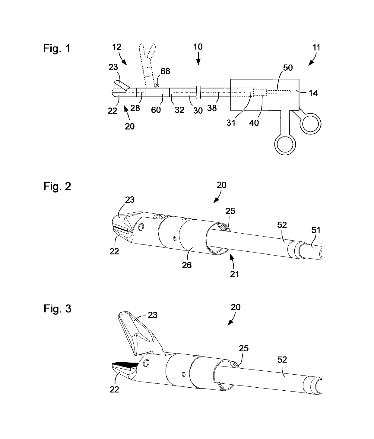
[0051]FIG. 1 shows a schematic illustration of a medical instrument 10 having a proximal end 11 and a distal end 12. The medical instrument 10 comprises at the proximal end 11 a handling device 14 and at the distal end 12 a tool 20. The handling device 14 comprises a plurality of grip parts, which are movable at least in part relative to one another. Furthermore, the handling device 14 may comprise further actuation devices, which are manually movable.

[0052]The handling device 14 and the tool 20 are mechanically interconnected by an outer shaft 30 and an articulation device 60. An inner shaft 40 and a transfer rod 50 are arranged concentrically in the outer shaft 30. In FIG. 1, only the proximal ends of the inner shaft 40 and of the transfer rod 50 are indicated. The inner shaft 40 and the transfer rod 50 are displaceable parallel with respect to the longitudinal axis 38 of the outer shaft and / or rotatable about the longitudinal axis 38, in each case independently of one another.

[00...


PUM


Abstract

An articulation device for a medical instrument includes a coupling for releasable mechanical connection of the articulation device to a tool or to the distal end of a shaft, a locking device on the coupling for locking the mechanical connection, and an articulation, which enables the coupling to be angled relative to an end of the articulation device remote from the coupling. The locking device is designed such that the mechanical connection is locked in a predetermined working angular position of the articulation and is releasable in a predetermined release angular position of the articulation.

Description

FIELD OF THE INVENTION[0001]The present invention is directed to a medical instrument with a bendable shaft and to an articulation device for a medical instrument.BACKGROUND OF THE INVENTION[0002]Medical instruments, in particular microinvasive surgical instruments, have a growing number of degrees of freedom. This allows medical staff to carry out increasingly complex activities and increasing numbers of different activities using a single instrument. For example, in the case of a needle holder or another gripping or cutting tool at the distal end of a long, thin shaft, the option to bend the tool relative to the shaft is desirable for some applications. A possibility of bending or pivoting the tool about an axis perpendicular with respect to the longitudinal axis of the shaft can enable gripping or cutting in a direction that otherwise cannot be reached.[0003]In the case of reusable medical instruments, the possibility of disassembling the tool as extensively as possible as a prer...

Claims


Application Information

Patent Timeline
Patent Type & Authority Patents(United States)
IPC IPC(8): A61B17/00A61B17/29A61B90/00
CPCA61B17/2909A61B17/00234A61B17/29A61B17/00A61B2090/0813A61B2017/2919A61B2017/0046A61B2017/2946A61B2017/2927A61B2017/2931A61B2017/2939A61B2017/00473A61B2017/00477A61B2017/291
Inventor KAERCHER, DANIELSTEFAN, JOCHEN
Owner KARL STORZ GMBH & CO KG
Learn More