
Display control apparatus, method for controlling the same, and storage medium

Active Publication Date: 2016-08-04
CANON KK
View PDF2 Cites 4 Cited by
  • Summary
  • Abstract
  • Description
  • Claims
  • Application Information

AI Technical Summary

Benefits of technology

The invention aims to improve the user experience when using a display on a finder by reducing poor usability and discomfort. This is achieved while also reducing power consumption.

Problems solved by technology

However, the EVF has a disadvantage in that, if a liquid crystal panel using backlight as lighting is used, power consumption is large.
Furthermore, if an organic electroluminescence (EL) panel is used, burn-in or aging degradation occurs if display is performed for a long period of time.
However, in the related art described above, a display portion in the EVF is blacked out when a user's eye is separated from the EVF for a short time, and a long period of time is required for energization when the eye is brought into contact with the EVF again resulting in poor usability.

Method used


Image

  • Display control apparatus, method for controlling the same, and storage medium
  • Display control apparatus, method for controlling the same, and storage medium
  • Display control apparatus, method for controlling the same, and storage medium

Examples


first embodiment

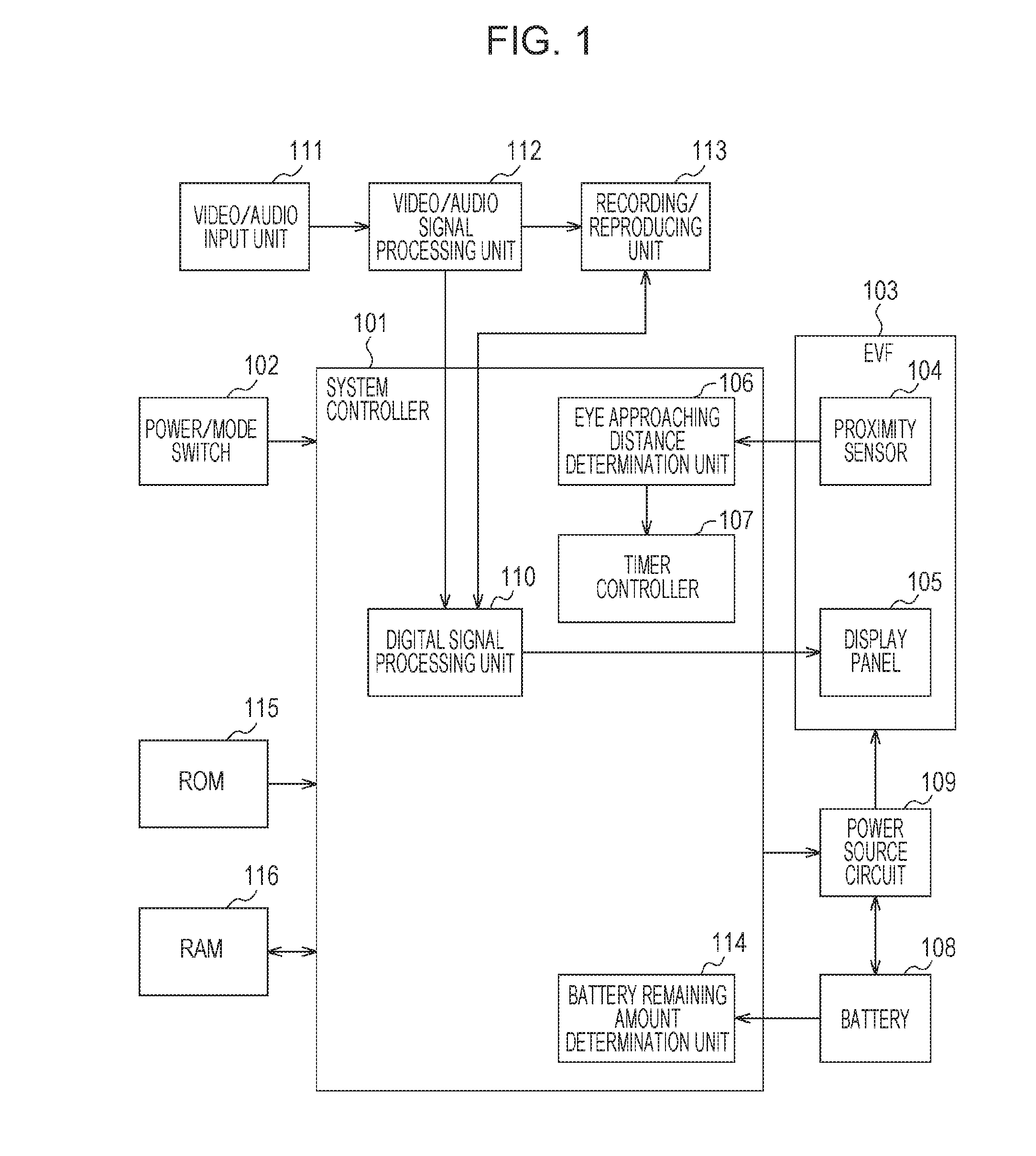
[0020]A configuration of an imaging apparatus according to a first embodiment of the present invention will be described hereinafter.

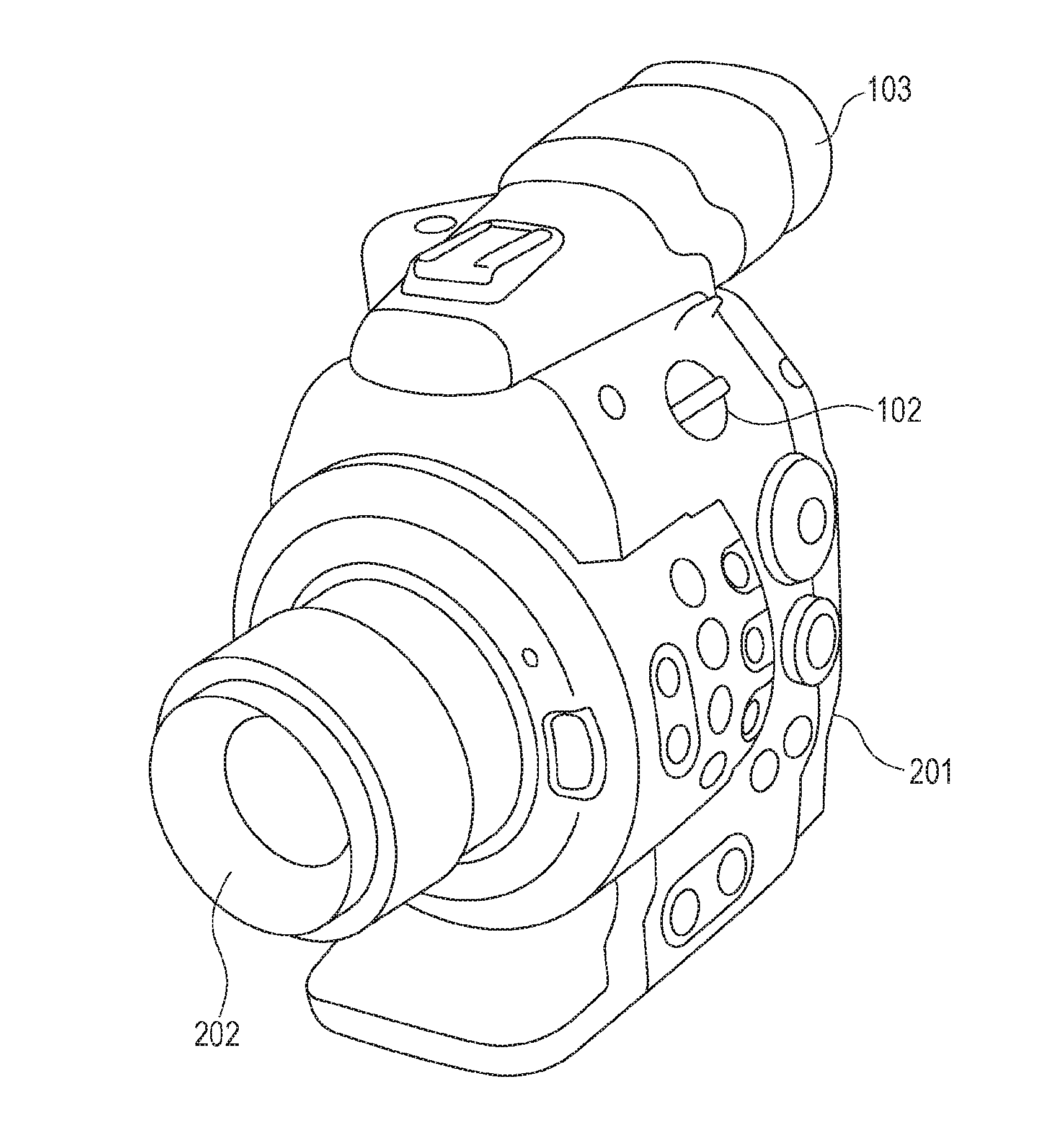
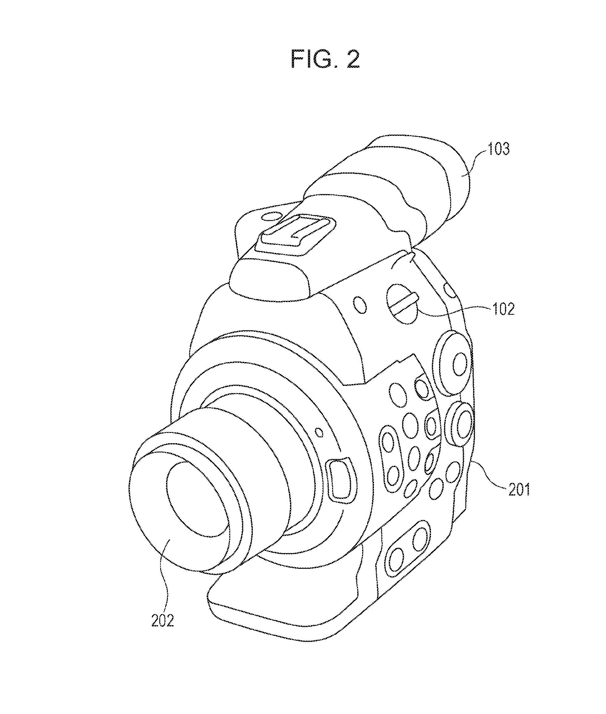
[0021]FIG. 2 is a perspective view illustrating appearance of the configuration of the imaging apparatus according to the embodiment.

[0022]In FIG. 2, a reference numeral 201 denotes a body of a video camera, 202 denotes a lens, 102 denotes a power / mode switch, and 103 denotes an EVF.

[0023]The video camera according to the first embodiment includes the lens 202 in a front portion of the camera body 201 and the EVF 103 incorporating a display unit in a rear portion of the camera body 201. Furthermore, a battery, not illustrated, may be attached to the rear portion. Specifically, the EVF 103 is constituted by an organic EL panel capable of displaying reproduced video images and captured video images and a proximity sensor, not illustrated, disposed in an eye contacting portion of the EVF 103.

[0024]The power / mode switch 102 performs an on / off operation of ...

second embodiment

[0064]Hereinafter, a configuration of an imaging apparatus according to a second embodiment of the present invention will be described. The configuration of the imaging apparatus and a system configuration according to the second embodiment of the present invention are the same as those of the first embodiment (FIGS. 1 and 2), and therefore, descriptions thereof are omitted.

[0065]Operation of the second embodiment will be described with reference to a flowchart hereinafter.

[0066]FIG. 5 is a flowchart illustrating operation of the imaging apparatus according to the second embodiment. This process is realized when a system controller 101 reads a program stored in a ROM 115 to a RAM 116 and executes the program.

[0067]In FIG. 5, when power is supplied from a power / mode switch 102, the system controller 101 determines whether an eye approaching distance detected by a proximity sensor 104 of an EVF 103 is smaller than a threshold value Th1 (a threshold value 1) in step S501. Threshold val...


PUM


Abstract

A display control apparatus includes a viewfinder including an eye contacting portion and an internal display unit, an eye approaching detection unit, a mode switching unit which selects one of a plurality of operation modes including first and second operation modes, and a control unit which performs control such that an on state of the internal display unit is changed to an off state based on detection, by the eye approaching detection unit, of an object which moves away from the eye contacting portion to a position at or further than a first distance from the eye contacting portion in the first operation mode, and the on state is changed to the off state based on detection, by the eye approaching detection unit, of an object which moves away from the eye contacting portion to a position at or further than a second distance, which is larger than the first distance, from the eye contacting portion in the second operation mode.

Description

BACKGROUND OF THE INVENTION[0001]1. Field of the Invention[0002]The present invention relates to a display control apparatus, a method for controlling the display control apparatus, and a storage medium, and particularly relates to a technique of controlling display by a display member included in an eyepiece finder.[0003]2. Description of the Related Art[0004]In recent years, digital still cameras including a finder in addition to an external display device have been widely used. Examples of such digital still cameras include digital still cameras having an optical finder and digital still cameras having an electronic viewfinder (hereinafter referred to as an “EVF”).[0005]The EVF is capable of displaying an image captured by an imaging element in real time, and therefore, is conveniently used to check an actually captured image. However, the EVF has a disadvantage in that, if a liquid crystal panel using backlight as lighting is used, power consumption is large. Furthermore, if an ...

Claims


Application Information

Patent Timeline
IPC IPC(8): H04N5/232
CPCH04N5/23241H04N5/23293H04N5/23245H04N23/50H04N23/611H04N23/651H04N23/667H04N23/63
Inventor WADA, TAKAYUKI
Owner CANON KK
Learn More