Projection system and projection-type image display apparatus
a projection system and projection type technology, applied in the direction of projectors, optics, instruments, etc., can solve the problems of insufficient application of each projection system for a large screen, and achieve the effects of wide field angle, high luminance, and high resolution
- Summary
- Abstract
- Description
- Claims
- Application Information
AI Technical Summary
Benefits of technology
Problems solved by technology
Method used
Image
Examples
example 1
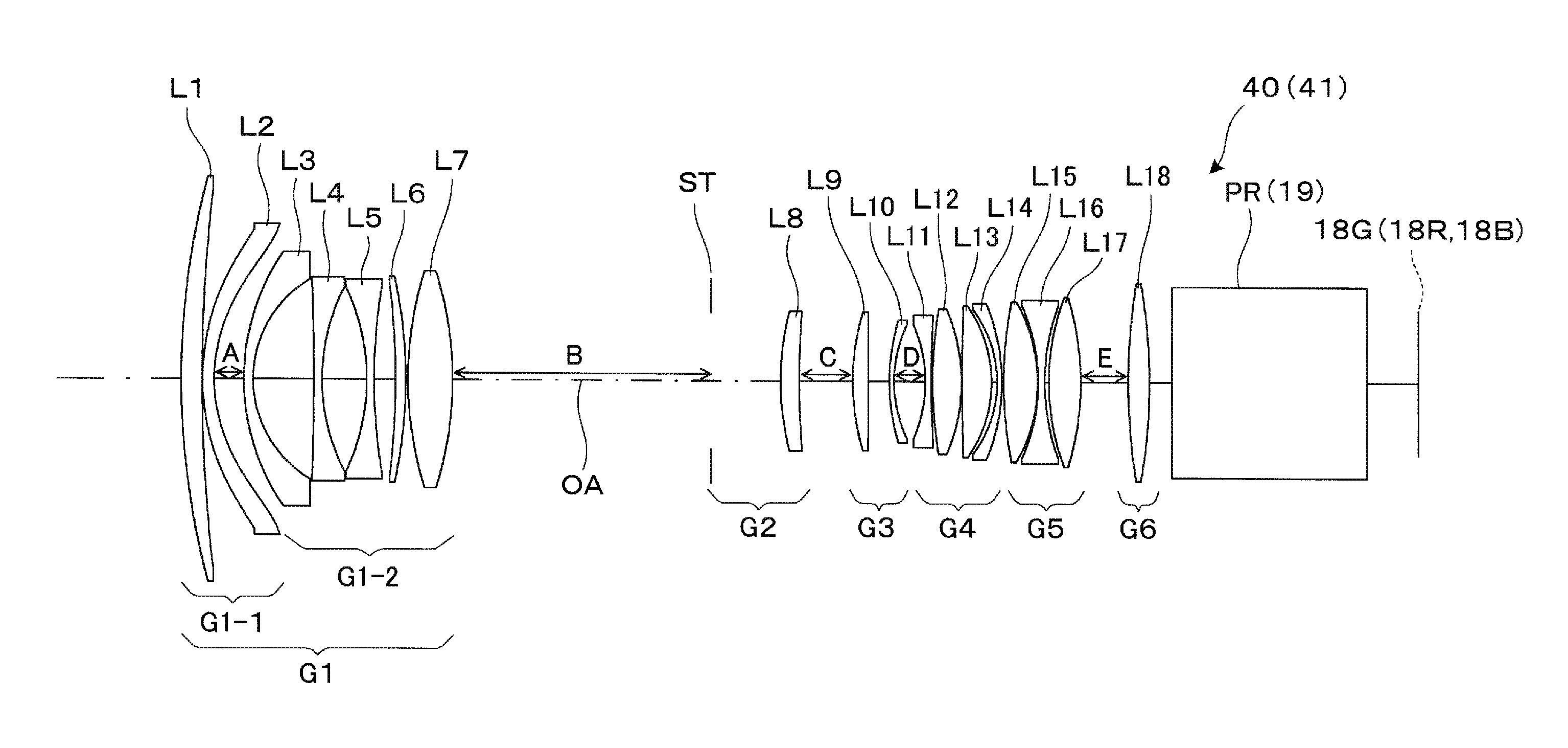
[0070]Table 1 shown below shows data on the lens surfaces of a projection lens according to Example 1. In Table 1 and other tables, “INF” stands for ∞.
TABLE 1SurfacenumberElementGroupRDndνd0SCINFOBJ1L11-1335.3769.0761.5163364.12702.8360.3003L2105.4395.0001.5311656.0471.594A5L31-296.7724.0001.8466623.8650.13126.5307L4−1007.6243.5001.6180063.4886.20019.4989L5−92.0243.2001.4370095.110242.9509.33711L6−335.7524.4601.8466623.812−205.3841.00013L7156.74219.4431.6034238.014−153.835B15ST2INF35.27616L8120.3208.2071.6989530.117373.545C18L93105.4776.7671.4874970.519−1968.3269.25320L1093.7802.0001.4970081.52157.203D22L114−60.9402.6001.9036631.323490.0860.57924L12190.11412.5751.8061033.325−79.7290.30026L131107.21112.8511.4970081.527−56.6742.47328L14−51.4562.0001.8061033.329−87.986E30L155176.14414.8941.4370095.131−68.9840.20032L16−80.1852.8001.8061033.33394.5071.86634L17104.78813.9541.4370095.135−123.359F36L186265.6769.2831.8080922.837−244.8161038DPINF851.516864.239INF22.4840LVINF0.00
[0071]Table 2 ...
example 2
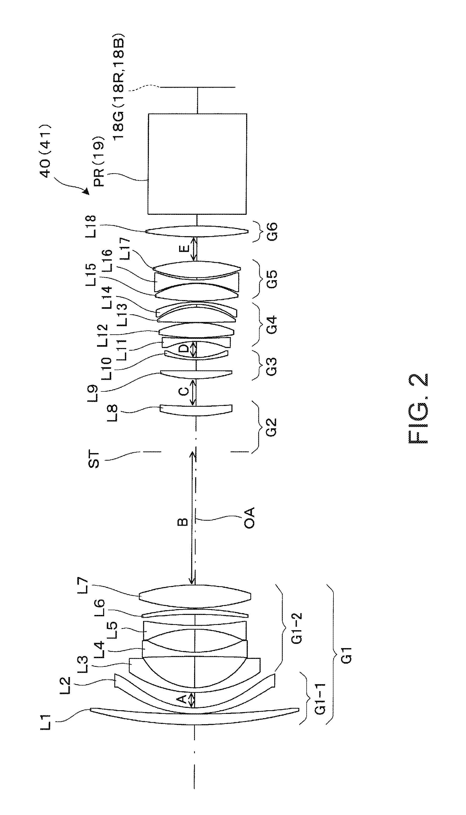
[0078]Table 5 shown below shows data on the lens surfaces of a projection system according to Example 2.
TABLE 5SurfacenumberElementGroupRDndνd0SCINFOBJ1L11-1348.9039.8311.5163364.12824.4050.3003L2115.4965.0001.5311656.0477.261A5L31-295.1794.0001.8466623.8650.32823.6657L4243.4293.5001.4970081.5866.73221.2699L5−112.2973.4061.4670081.510122.3400.30011L697.27515.7181.5163364.112−1587.133B13L721045.1869.4621.8466623.814−266.623C15L83114.1306.6541.7234238.016193.518D17L94107.36311.8671.4874970.218−2063.8369.46119L10102.0992.0001.4370095.12060.410E21L115−61.4052.6001.9036631.322497.2810.55323L12191.82612.5981.8061033.324−81.7230.30025L13576.70912.8841.4970081.526−60.6672.34827L14−55.5062.0001.8061033.328−90.596F29L156149.43515.0371.4370095.130−75.2730.70531L16−80.9302.8001.8061033.33293.4871.70733L17101.03515.2721.4370095.134−116.868G35L187229.3358.8001.8080922.836−334.28910.00037DPINF80.0001.516864.238INF22.67340LVINF0
[0079]Table 6 shown below shows aspheric coefficients of a third surfac...
example 3
[0086]Table 9 shown below shows data on the lens surfaces of a projection system according to Example 3.
TABLE 9SurfacenumberElementGroupRDndνd0SCINFOBJ1L11-1297.83010.3801.5163364.12663.9620.3003L2108.9475.0001.5311656.0473.023A5L31-292.5204.0001.8466623.8648.90726.9257L4−787.2823.5001.6180063.4883.70119.1519L5−90.4575.0001.4370095.110337.199B11L62−161.9084.2091.8466623.812−130.1901.00013L7163.93818.5831.6034238.014−157.341C15ST3INF33.16516L8110.40412.3711.6989530.117283.989D18L94115.3916.8401.4874970.219−622.82111.85120L1084.2932.0001.4970081.52153.174E22L115−62.4552.6001.9036631.323452.2160.69724L12189.91711.6981.8061033.325−87.6320.30026L131539.78412.9581.4970081.527−53.1782.36028L14−48.7982.0001.8061033.329−87.500F30L156164.10915.1951.4370095.131−68.9830.20032L16−87.0512.8001.8061033.33394.4681.80434L17103.82414.1631.4370095.135−121.317G36L187218.3229.6741.8080922.837DP−288.92710.00038INF80.0001.516864.239LVINF22.691
[0087]Table 10 shown below shows aspheric coefficients of a thi...
PUM
 Abstract
Description
Claims
Application Information
 - R&D
- Intellectual Property
- Life Sciences
- Materials
- Tech Scout
- Unparalleled Data Quality
- Higher Quality Content
- 60% Fewer Hallucinations
Browse by: Latest US Patents, China's latest patents, Technical Efficacy Thesaurus, Application Domain, Technology Topic, Popular Technical Reports.
© 2025 PatSnap. All rights reserved.Legal|Privacy policy|Modern Slavery Act Transparency Statement|Sitemap|About US| Contact US: help@patsnap.com


