Strain release in pfet regions

a technology of pfet and region, applied in the field of pfet region, can solve the problems of 8 to 15% performance compromise of pfet finfet devices

Active Publication Date: 2016-07-14
IBM CORP
View PDF7 Cites 15 Cited by
  • Summary
  • Abstract
  • Description
  • Claims
  • Application Information

AI Technical Summary

Problems solved by technology

When the global intrinsic stresses in an SSOI substrate exceed a predetermined maximum value (e.g., greater than about 1 GPa), however, the performance of pFET finFET devices may be compromised by 8 to 15%.

Method used


Image

  • Strain release in pfet regions
  • Strain release in pfet regions
  • Strain release in pfet regions

Examples


Embodiment Construction

[0017]Detailed embodiments of the claimed structures and methods are disclosed herein; however, it is to be understood that the disclosed embodiments are merely illustrative of the claimed structures and methods that may be embodied in various forms. In addition, each of the examples given in connection with the various embodiments is intended to be illustrative, and not restrictive. Further, the figures are not necessarily to scale, some features may be exaggerated to show details of particular components. Therefore, specific structural and functional details disclosed herein are not to be interpreted as limiting, but merely as a representative basis for teaching one skilled in the art to variously employ the methods and structures of the present disclosure.

[0018]References in the specification to “one embodiment”, “an embodiment”, “an example embodiment”, etc., indicate that the embodiment described may include a particular feature, structure, or characteristic, but every embodime...


PUM


Abstract

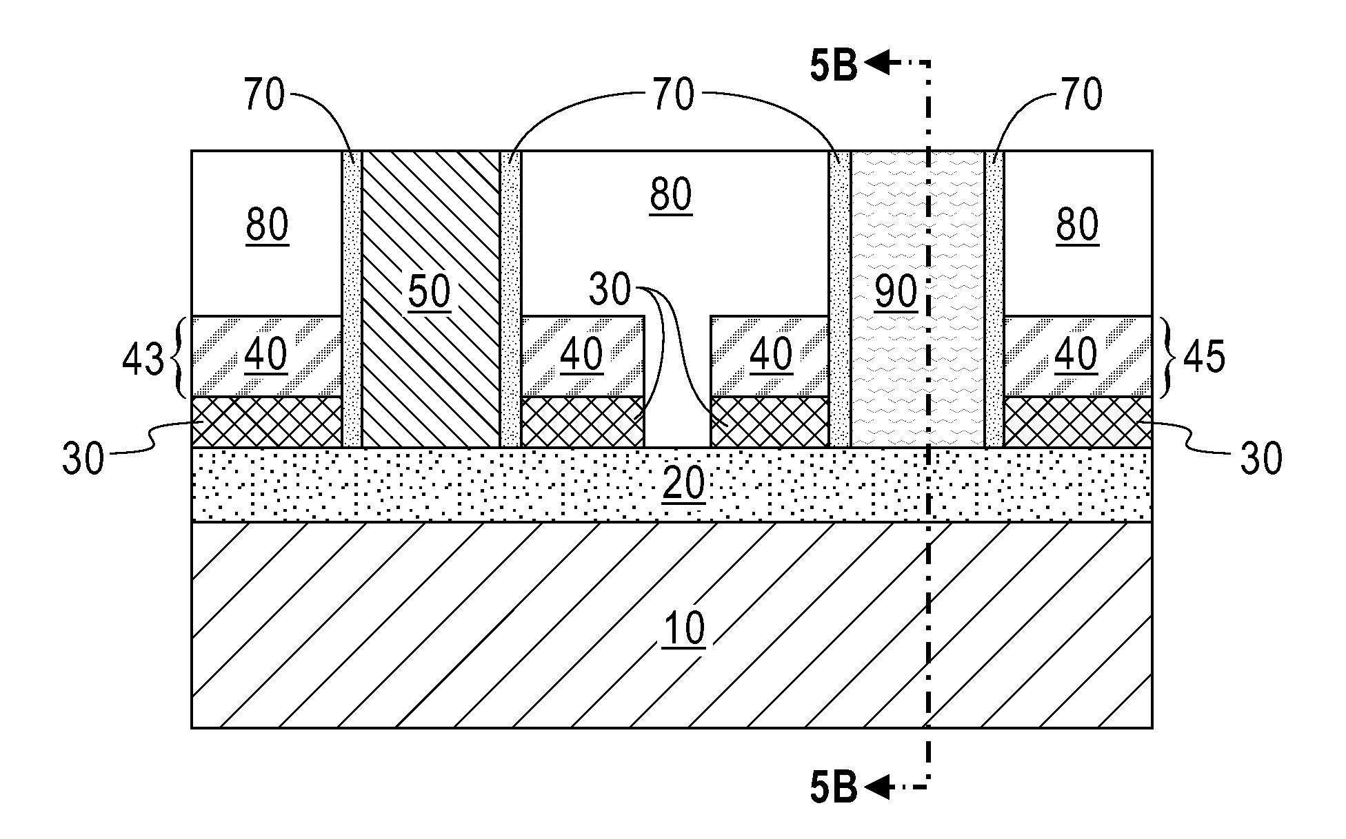
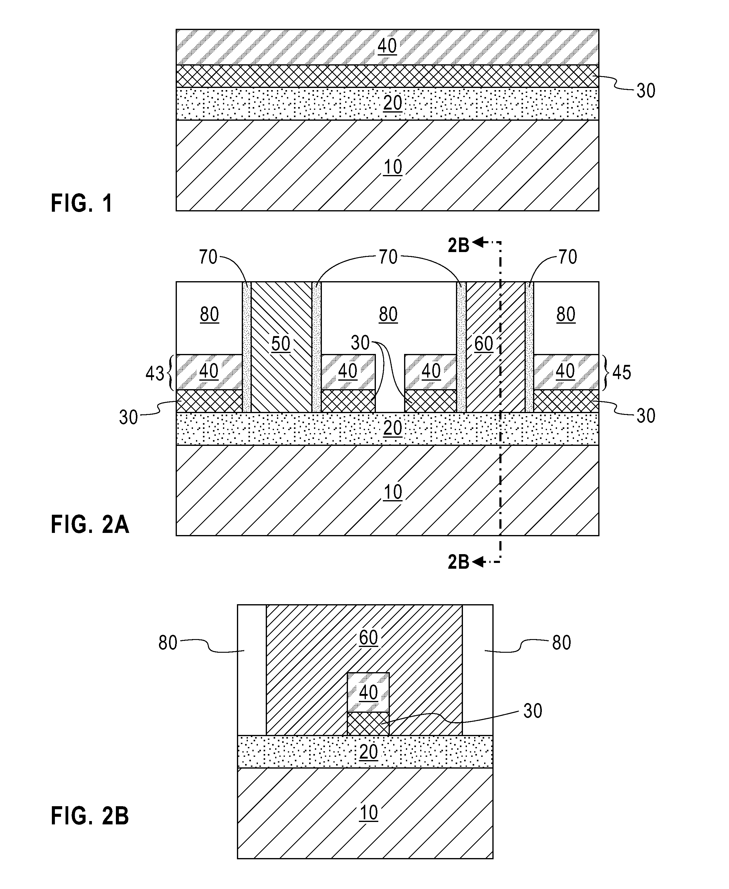
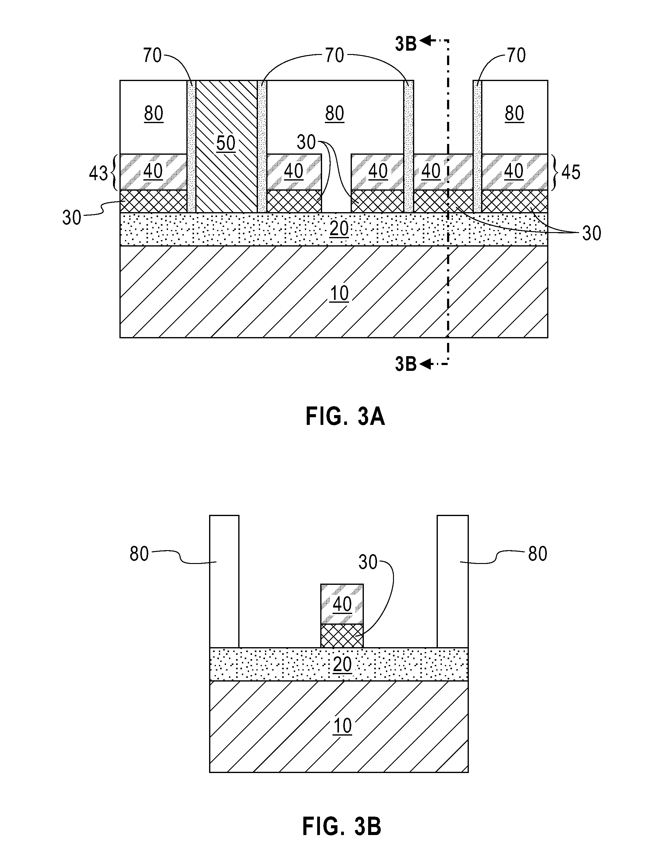
A method for fabricating a semiconductor device, includes providing a strained silicon on insulator (SSOI) structure, the SSOI structure comprises, a dielectric layer disposed on a substrate, a silicon germanium layer disposed on the dielectric layer, and a strained semiconductor material layer disposed directly on the silicon germanium layer, forming a plurality of fins on the SSOI structure, forming a gate structure over a portion of at least one fin in a nFET region, forming a gate structure over a portion of at least one fin in a pFET region, removing the gate structure over the portion of the at least one fin in the pFET region, removing the silicon germanium layer exposed by the removing, and forming a new gate structure over the portion of the at least one fin in the pFET region, such that the new gate structure surrounds the portion on all four sides.

Description

BACKGROUND OF THE INVENTION[0001]The present invention relates generally to semiconductor devices, and more particularly to utilizing strained silicon-on-insulator (SSOI) substrates for nFET regions with strain release in pFET regions.[0002]A complementary metal oxide semiconductor device (CMOS) uses complementary and symmetrically-oriented pairs of p-type and n-type metal oxide semiconductor field effect transistors (MOSFETs) arranged on silicon or silicon on insulator (SOI) substrates. A MOSFET, which is used for amplifying or switching electronic signals for logic functions, has source and drain regions connected by a channel. The source region is a terminal through which current in the form of majority charge carriers electrons or holes) enters the channel, and the drain region is a terminal through which current in the form of majority charge carriers leaves the channel. In a p-type MOSFET (hereinafter “pFET”), the majority charge carriers are holes that flow through the channe...

Claims


Application Information

Patent Timeline
Patent Type & Authority Applications(United States)
IPC IPC(8): H01L27/12H01L21/3065H01L29/78H01L27/092H01L29/66H01L21/84H01L29/161
CPCH01L27/1211H01L21/845H01L21/3065H01L29/7849H01L27/0924H01L29/66545H01L29/161H01L29/42392H01L29/78696H01L21/823807H01L21/823821H01L29/1054H01L21/76251
Inventor CHENG, KANGGUODORIS, BRUCE B.KHAKIFIROOZ, ALILU, DARSEN D.REZNICEK, ALEXANDERRIM, KERN
Owner IBM CORP
Why Eureka
Try Eureka