
Trailer for autonomous vehicle

a technology of autonomous vehicles and trailers, applied in the direction of load securing, transportation items, instruments, etc., can solve the problems of high cost of satellite manufacture, deployment and operation, and many drawbacks of satellite reconnaissance,

Active Publication Date: 2016-07-14
SILICIS TECH
View PDF11 Cites 19 Cited by
  • Summary
  • Abstract
  • Description
  • Claims
  • Application Information

AI Technical Summary

Benefits of technology

The patent describes a trailer for an autonomous vehicle that can be controlled and adjusted through a command and control interface. The trailer can be expanded to increase its footprint and includes sensors to monitor environmental data. The trailer also includes a power distribution system and a gas containment system to provide energy to the autonomous vehicle. The trailer can be equipped with a fairlead to guide the tether and a mast to receive payloads from the autonomous vehicle. The trailer can also include a detachable portion to extend its footprint and a cocoon to encapsulate the autonomous vehicle. The technical effects of this patent include improved control and adjustability of the trailer for autonomous vehicles and increased safety and efficiency during deployment and operation.

Problems solved by technology

Satellite reconnaissance, however, suffers from many drawbacks.
For example, satellites are very costly to manufacture, deploy and operate.
The process of changing the position of a satellite is costly and cumbersome.
Furthermore, some satellites are not configured to provide continuous high resolution video monitoring of an area.
However, these aerial vehicles also suffer from drawbacks.
For example, the length of time an aerial vehicle can remain above a particular area is limited to amount of fuel and / or battery charge onboard the vehicle.
In addition, operational costs of these vehicles can also be high and prohibitive of widespread use.
In fact, the cost of operation alone is a limiting factor for widespread use of these vehicles in modern reconnaissance operations.

Method used


Image

  • Trailer for autonomous vehicle
  • Trailer for autonomous vehicle
  • Trailer for autonomous vehicle

Examples


Embodiment Construction

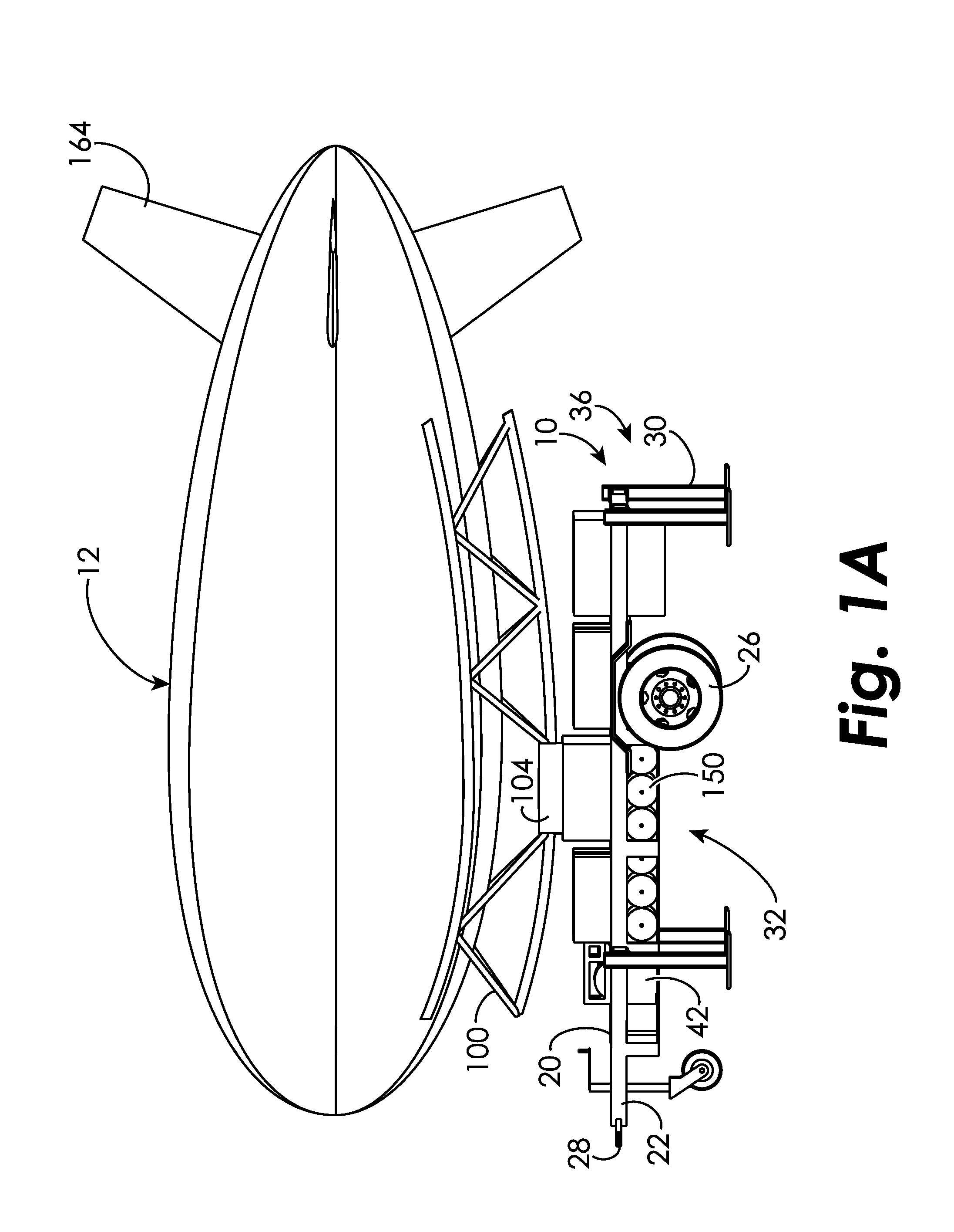
[0006]The disclosed embodiments include a trailer for an autonomous vehicle controlled by a command and control interface. The trailer includes a trailer body configured to retain the autonomous vehicle in an undeployed configuration. The trailer also anchors the autonomous vehicle in a deployed configuration. A tether is provided having a first end coupled to the trailer body and a second end that is configured to couple to the autonomous vehicle. A winch is utilized to adjust a length of the tether to move the autonomous vehicle between the undeployed configuration and deployed configuration. Further, a communication system communicates with the command and control interface and the autonomous vehicle to control movement of the autonomous vehicle between the undeployed configuration and deployed configuration.

[0007]In one embodiment, the command and control interface is positioned remotely from the trailer body and the communication system communicates with the command and control...


PUM


Abstract

The disclosed embodiments include a trailer for an autonomous vehicle controlled by a command and control interface. The trailer includes a trailer body configured to retain the autonomous vehicle in an undeployed configuration. The trailer also anchors the autonomous vehicle in a deployed configuration. A tether is provided having a first end coupled to the trailer body and a second end that is configured to couple to the autonomous vehicle. A winch is utilized to adjust a length of the tether to move the autonomous vehicle between the undeployed configuration and deployed configuration. Further, a communication system communicates with the command and control interface and the autonomous vehicle to control movement of the autonomous vehicle between the undeployed configuration and deployed configuration.

Description

CROSS-REFERENCE TO RELATED APPLICATIONS[0001]The present application claims priority to U.S. Provisional Patent Application Ser. No. 61 / 876,278 filed Sep. 11, 2013 and having the title “TRAILER FOR AUTONOMOUS VEHICLE”, which is herein incorporated in its entirety.TECHNICAL FIELD OF THE DISCLOSED EMBODIMENTS[0002]The present disclosure generally relates to autonomous or semi-autonomous aircraft and other vehicles and a system and method for controlling aircraft and other vehicles.BACKGROUND OF THE DISCLOSED EMBODIMENTS[0003]Since the early days of intelligence satellites, aerial surveillance and reconnaissance has been a paramount feature of the intelligence community. Satellite reconnaissance, however, suffers from many drawbacks. For example, satellites are very costly to manufacture, deploy and operate. In addition, in order to monitor a particular area on the ground, the position of a geosynchronous orbit satellite may need to be changed. The process of changing the position of a...

Claims


Application Information

Patent Timeline
IPC IPC(8): B60P3/11B64B1/66B64C39/02B60P7/06B60P7/08
CPCB60P3/11B60P7/06B60P7/0876B64C2201/12B64C39/022B64B1/66B64C39/024B64B1/10B64B1/50B64B1/58B64F1/14B64F3/02G08C17/02B64U10/30B64U2101/35B64U2201/202B64U80/86B64U70/99B64U70/90B64U80/25B64U50/32B64U70/92B64U10/60B64U2201/20
Inventor STIGLER, MICHAEL J.SETAR, NICHOLAS JAMES
Owner SILICIS TECH
Learn More