Method of manufacturing rotogravure cylinders

a technology of rotogravure cylinder and aluminum base, which is applied in the direction of superimposed coating process, liquid/solution decomposition chemical coating, lithography, etc., can solve the problems of limited use of aluminum for the base of the cylinder, less difficulty in electro-copper plate, etc., to achieve the effect of improving the reliability of the cylinder, reducing the cost of production, and improving the quality of production

Active Publication Date: 2016-07-14
ICR IOANNOU SA
View PDF17 Cites 3 Cited by
  • Summary
  • Abstract
  • Description
  • Claims
  • Application Information

AI Technical Summary

Benefits of technology

[0024]It is an advantage of the present invention that the manufacturing process of gravure cylinder with aluminum base is greatly simplified. Particularly, in one preferred embodiment, a roughening treatment of the surface of the cylinder base may be eliminated. Moreover, plating processes, such as copper plating and chromium plating as used in the prior art may be and preferably are left out.
[0025]The engraving layer is suitably deposited with a thermal spraying coating process, in which the material is deposited in the form of particles. More preferably, a high velocity spraying process is used. In such a process, the coating material particles are applied with a high speed onto the cylinder, for instance with a speed of at least 300 m / s. More preferably, the velocity is higher, for instance above 600 m / s or even in the range of 900-1000 m / s. Such a particle velocity typically corresponds with a jet velocity that is even higher, for instance 1,200-1,400 m / s. Suitably, the particles have an average diameter of less than 50 μm, for instance in the range of 40-50 μm. Suitably, the cylinder herein rotates during the deposition process. The particles will impact on the cylindrical base, which results in liberation of a significant amount of energy in the form of heat. This heat will warm up the particles so as to melt at least partially. It is believed that such partial melting leads to better bonding, for instance by means of incorporated compressive stress.
[0026]In one embodiment, the engraving layer is deposited with a thickness of at least 300 μm, more preferably at least 400 μm. This thickness is deemed beneficial for stabilisation purposes. The layer thickness may even be higher than this, for instance in the order of 500-800 μm, so as to modify the diameter of the cylinder base. This is for instance suitable in the event of refurbishment of a recycled rotogravure cylinder, such as described in the non-prepublished application PCT / EP2013 / 050228, which is included herein by reference.
[0027]Preferably, the engraving layer is thinned after its deposition, suitably by at least 100 μm, more preferably at least 150 μm. This thinning is for instance carried out by lathing or grinding. A lubricant solution may be applied simultaneously with the cooling. Use is suitably made herein of grinding with a conventional grinding machine with grinding and polishing stones. Such thinning is preferred to ensure that the resulting surface of the engraving layer has a predefined shape, more particularly is most perfectly cylindrical, in accordance with requirements.
[0028]More preferably, the surface is then polished to achieve the desired roughness Rz between 0.35 and 0.60 μm, and more preferably between 0.4-0.45 μm. The polished circumferential layer is then suitable for engraving, particularly with laser etching.
[0029]It is an advantage of this invention that the resulting rotogravure cylinder surface has the hardness to withstand wear in the printing process without the need for chromium plating. It is also a significant advantage of this invention that the electrolytic plating processes (pre-copper plating, copper plating and chromium plating) may be eliminated.

Problems solved by technology

However, aluminum is an electrochemically passive material and it is quite challenging to electro-copper plate it.
This has limited the use of aluminium for the base of the cylinder.
In further investigations on the cylinders manufactured in accordance with WO2011 / 073695A2 it was however observed that the reliability of the cylinders was less than desired.
Particularly, about 1-5% of the cylinders turned out defect relatively quickly after use by the customer.
However, the defects came irregularly, in an unpredictable manner.
Such defect clearly resulted in a need for replacement of the defect cylinders, which is undesired.
The inherent disadvantage of the prior art is the use of electrolytic baths that constitutes a hazard to the environment and to humans.

Method used


Image

  • Method of manufacturing rotogravure cylinders
  • Method of manufacturing rotogravure cylinders
  • Method of manufacturing rotogravure cylinders

Examples


example 1

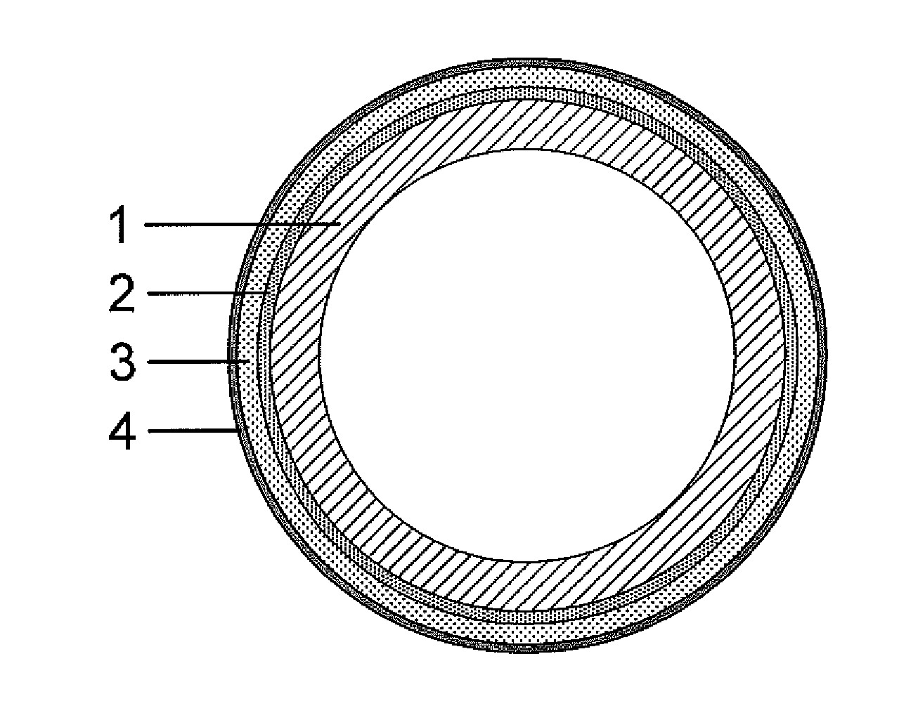
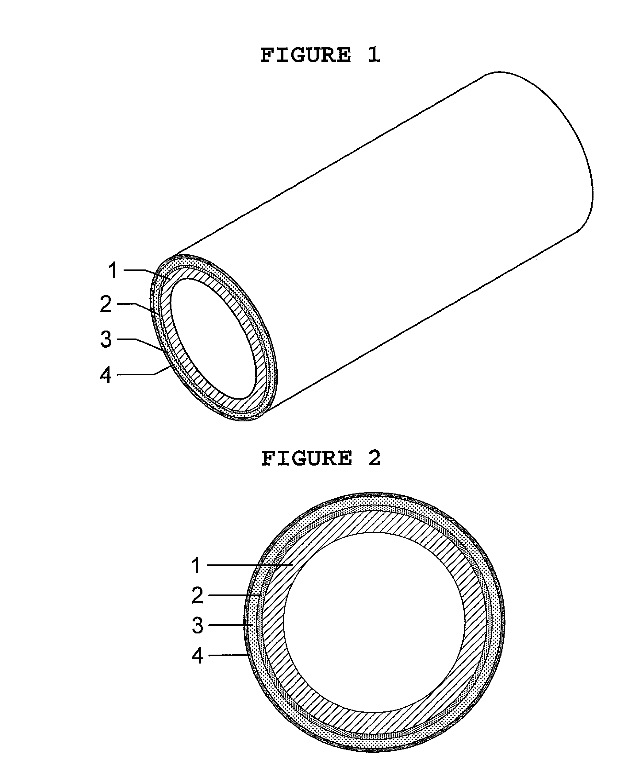
[0042]A gravure cylinder with a conventional steel base was produced to the desired dimensions. The steel cylinder was provided with a coating layer, for instance based on electroplated copper. Brass particles, with an average diameter of less than 50 μm, preferably in the range of 40-45 μm, were sprayed with a thermal spraying method. The brass in use was for instance common brass or high brass, containing 35-40 wt % zinc. During the spraying process, the cylinder was rotated. Impact of the brass particles onto the cylinder resulted in in heating up of the particles, to the extent of at least partial melting. This melting resulted in formation of a single layer extending circumferential around the base. Compressive stress developed in the course of cooling down. This cooling down was achieved by waiting in one embodiment; in an alternative embodiment, jetted air was sprayed onto the cylinder with the circumferential layer.

[0043]The engraving layer was deposited in a thickness of ap...

example 2

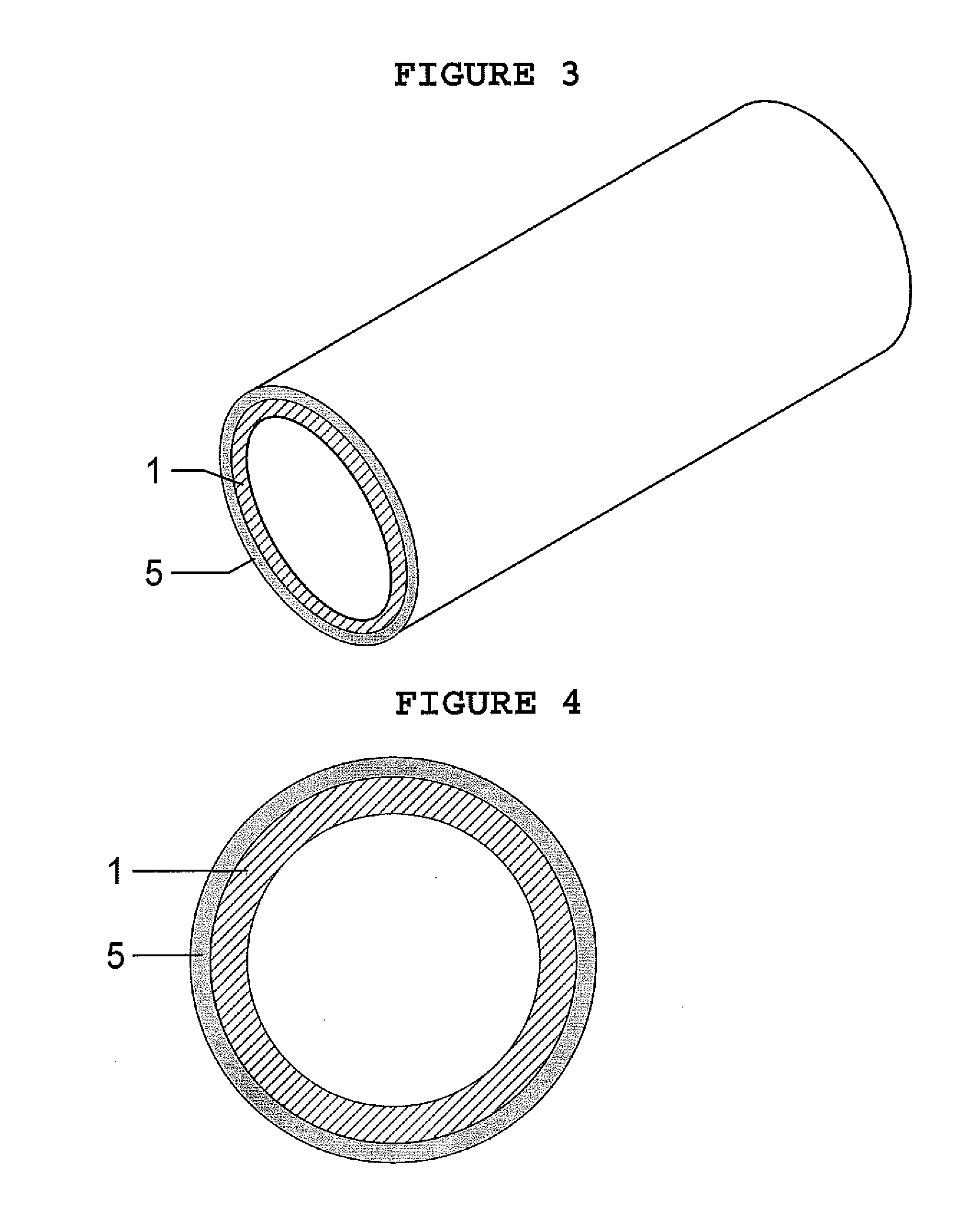
[0045]A second gravure cylinder was produced on the basis of a cylinder with an aluminium base. This aluminium base was produced from an aluminum tube to the desired dimensions. The brass particles of the type used in Example 1 were sprayed onto the aluminum base directly by means of high-velocity thermal spraying, in which the particle speed was generally above 300 m / s, typically in the order of 700-1,200 m / s. The thickness of the deposited engraving layer was again set to 400 μm, which was subsequently thinned and polished.

example 3

[0046]The rotogravure cylinder manufactured in accordance with Example 1 was tested. Use was made of Vickers Hardness testing. This testing, standardized per se under ASTM E92 and ISO6507 was measured with the ultrasonic contact impedance (UCI) measurement, standardized under ASTM A 1038, using a diamond pyramid with a 136° roof angle. Measurement equipment for testing the Vickers Hardness on a surface with UCI measurement is commercially available from various suppliers. The Vickers Hardness is tested at room temperature, i.e. 20-25° C. The resulting Vickers Hardness was 430 HV.

[0047]Although the above description is the recommended methodology for the manufacturing of a light weight gravure cylinder with a base made of aluminum and a circumferential single layer engraved appropriately, it is apparent that appropriate deviations or alterations or modifications can be implemented without significant deviations from the present invention.

[0048]In summary, the invention relates to a g...


PUM

PropertyMeasurementUnit
Vickers Hardnessaaaaaaaaaa
surface roughness Rzaaaaaaaaaa

Abstract

The present invention describes a method for manufacturing rotogravure cylinders with a cylinder base made of aluminum and a single metallic layer on the cylinder surface. The method comprises the construction of the cylinder base, the deposition of the metallic layer on the cylinder surface, the thinning of the cylinder to achieve the required dimensions, the polishing of the cylinder surface and finally the etching of the cylinder with the desired printing pattern. The metallic layer can be any copper alloy that will produce a surface with a Vickers hardness of about 400 HV. The metallic layer is deposited onto the cylinder base using any thermal spraying method. The cylinder surface is then thinned and polished by using any conventional method. Finally, the cylinder is etched to provide a superb cylinder for the printing industry.

Description

FIELD OF THE INVENTION[0001]The present invention relates to a rotogravure cylinder comprising a cylindrical base and an engraving layer. The invention further relates to a method for manufacturing such rotogravure or gravure cylinders and to the use of the rotogravure cylinders, for instance in the printing industry for the printing of packaging materials (by transfer of ink from the printing cylinder to the packaging material), such as for instance Intaglio printing processes.BACKGROUND OF THE INVENTION[0002]Gravure cylinders comprise of a base cylinder, which is usually made of steel or aluminum (1, FIG. 1), a “soft” copper layer (2, FIGS. 1 and 2, FIG. 2) usually 10 μm thick, a “hard” copper layer usually 0.5 to 1 mm thick (3, FIGS. 1 and 3, FIG. 2) and a protection layer, which is usually a chromium layer typically 6 to 8 μm thick (4, FIGS. 1 and 4, FIG. 2).[0003]The “hard” copper layer is electroplated on the base of the cylinder and forms the surface which is engraved or etch...

Claims


Application Information

Patent Timeline
Patent Type & Authority Applications(United States)
IPC IPC(8): B41F3/54B41C1/00
CPCB41C1/00B41F3/54B41C1/02B41C1/05B41C1/18B41N1/06B41N1/12B41N1/20
Inventor IOANNOU, IOANNIS
Owner ICR IOANNOU SA
Why Eureka
Try Eureka