
Low Aberration, High Intensity Electron Beam For X-Ray Tubes

Active Publication Date: 2016-06-30
GENERAL ELECTRIC CO
View PDF6 Cites 4 Cited by
  • Summary
  • Abstract
  • Description
  • Claims
  • Application Information

AI Technical Summary

Benefits of technology

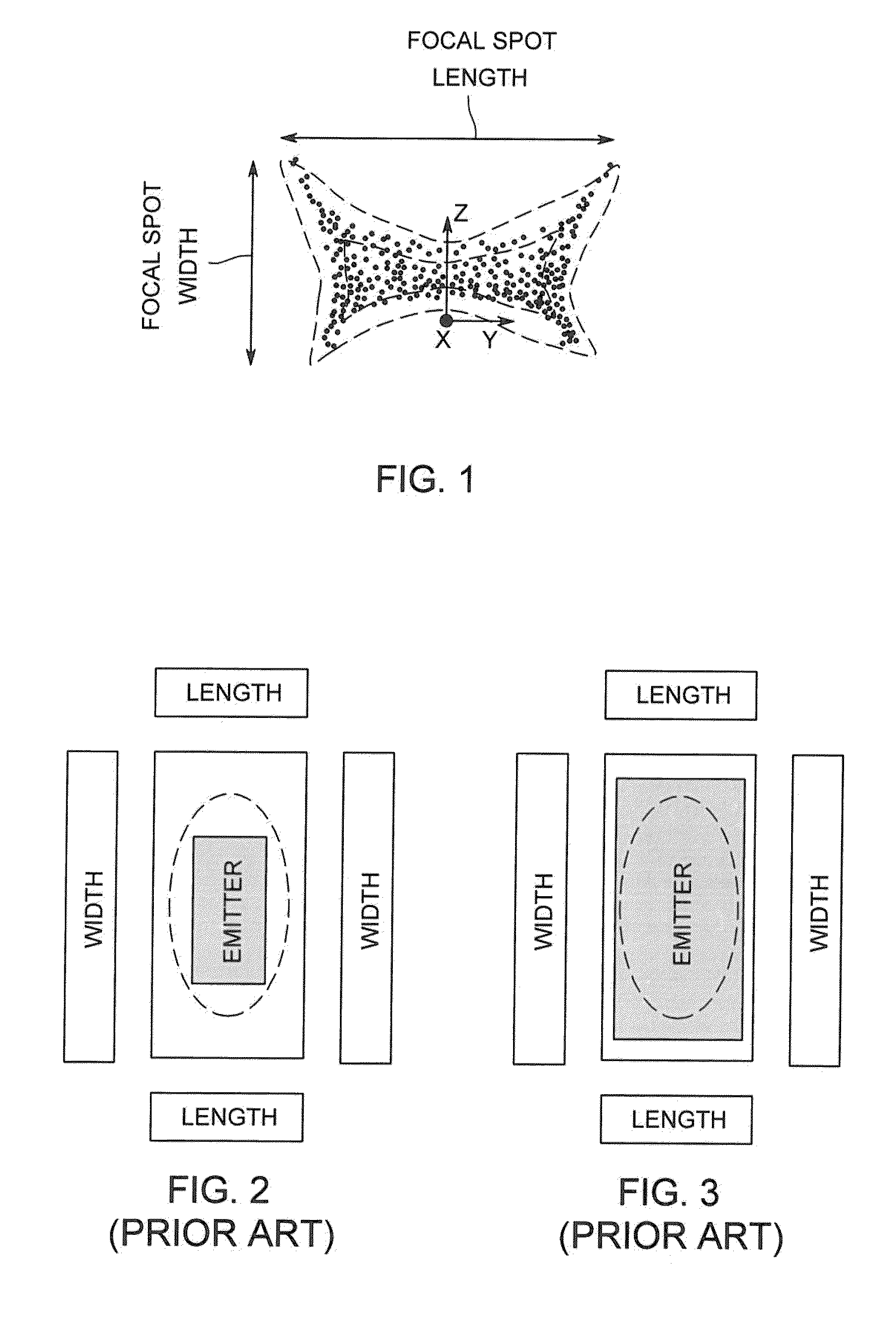
[0013]In the present invention, for maximum emission a cathode is formed with a large area flat emitter. To reduce the aberrations to a minimum the emission area in the flat emitter has a non-rectangular shape. In an exemplary embodiment, the flat emitter has a non-rectilinear polygonal shape for an emission area on the emitter in order to increase the emission current from the emitter at standard voltage levels without the need to r

Problems solved by technology

Accordingly, it is very difficult to focus all electrons into a small focal spot.
Due to the complex electron emission pattern from a cylindrical filament, focal spots resulting therefrom can have non-uniform profiles that are highly sensitive to the placement of the filament within the cup.
D-shaped filaments, however, are expensive to produce (they are typically formed about a D-shaped mandrel) and typically require, as well, very tight manufacturing tolerances and separately biased focus elec

Method used


Image

  • Low Aberration, High Intensity Electron Beam For X-Ray Tubes
  • Low Aberration, High Intensity Electron Beam For X-Ray Tubes
  • Low Aberration, High Intensity Electron Beam For X-Ray Tubes

Examples


Example

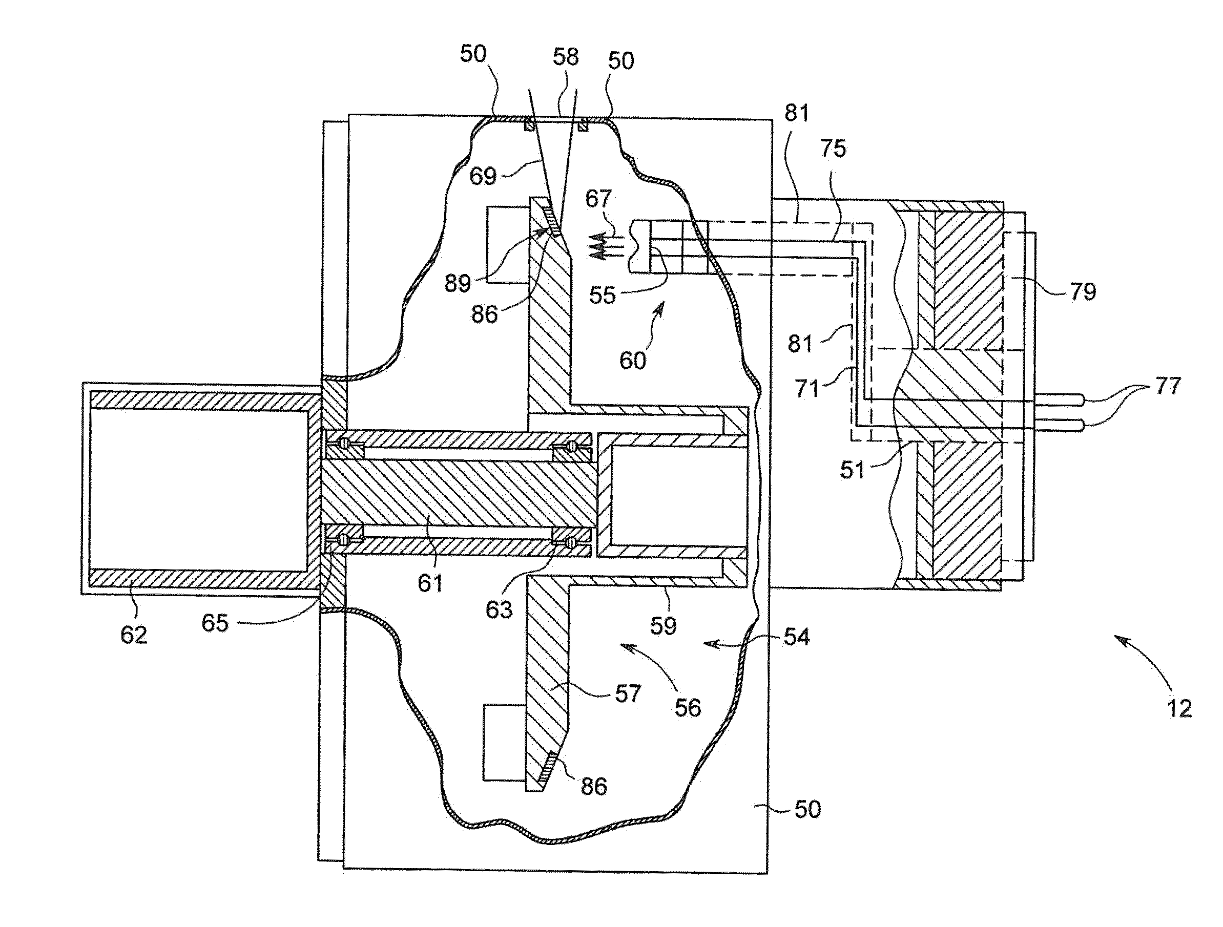
DETAILED DESCRIPTION OF THE DRAWINGS

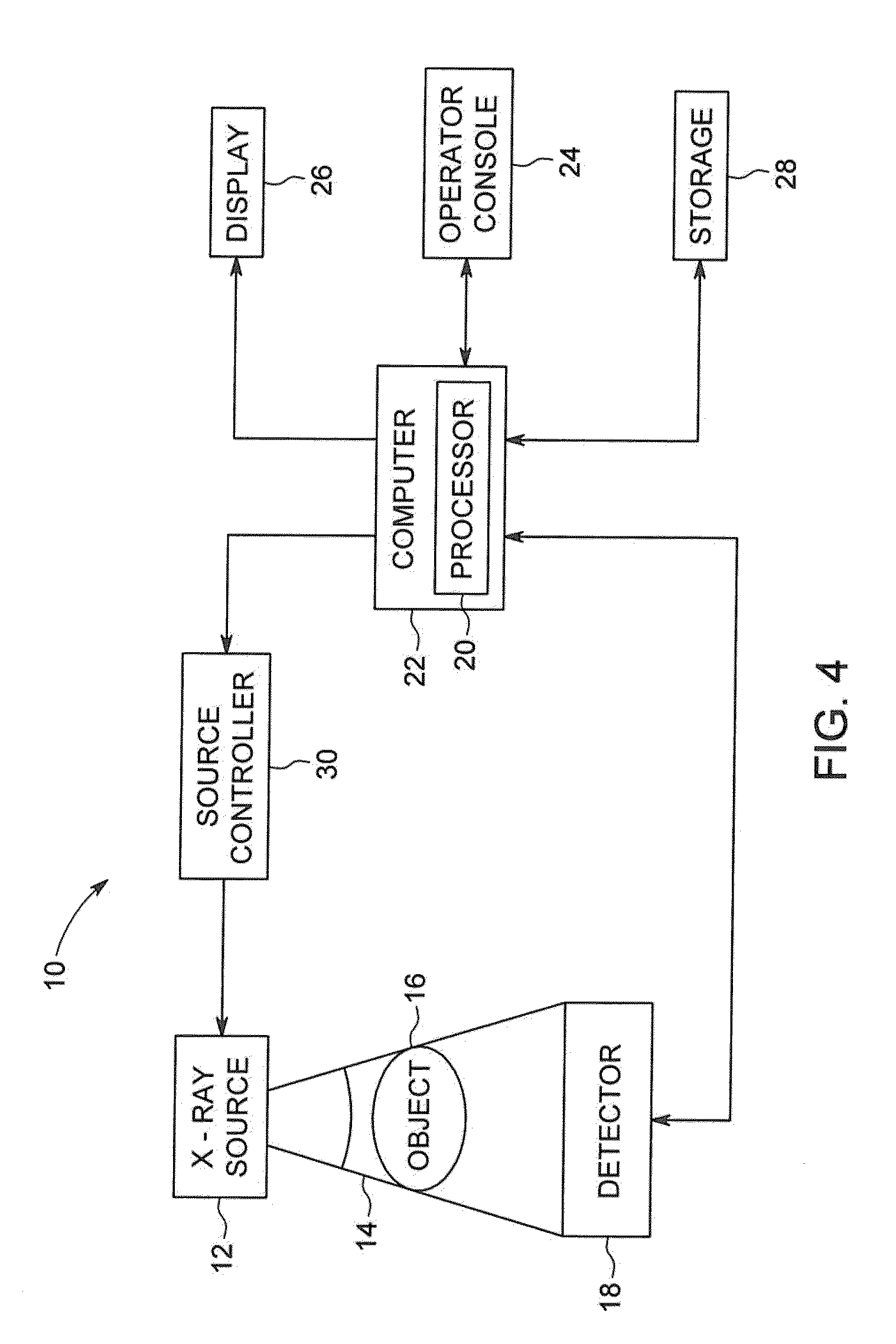
[0029]FIG. 4 is a block diagram of an embodiment of an imaging system 10 designed both to acquire original image data and to process the image data for display and / or analysis in accordance with embodiments of the invention. It will be appreciated by those skilled in the art that embodiments of the invention are applicable to numerous medical imaging systems implementing an x-ray tube, such as x-ray or mammography systems. Other imaging systems such as computed tomography (CT) systems and digital radiography (RAD) systems, which acquire image three dimensional data for a volume, also benefit from embodiments of the invention. The following discussion of x-ray system 10 is merely an example of one such implementation and is not intended to be limiting in terms of modality,

[0030]As shown in FIG. 4, x-ray system 10 includes an x-ray source 12 configured to project a beam of x-rays 14 through an object 16. Object 16 may include a human subject, pieces...


PUM


Abstract

In the present invention, a cathode for an x-ray tube is formed with a large area flat emitter. To reduce the aberrations to a minimum the emission area in the flat emitter has a non-rectangular shape and focusing pads arranged around the emitter. In an exemplary embodiment, the flat emitter has a non-rectilinear polygonal shape for an emission area on the emitter in order to increase the emission current from the emitter at standard voltage levels without the need to run the emitters at a higher temperature, add additional emitters to the cathode and/or to coat the emitters with a low work function material.

Description

BACKGROUND OF INVENTION[0001]The subject matter disclosed herein relates to X-ray tubes, and in particular, to X-ray cathode systems and X-ray cathodes.[0002]Presently available medical x-ray tubes typically include a cathode assembly having an emitter and a cup. The cathode assembly is oriented to face an x-ray tube anode, or target, which is typically a planar metal or composite structure. The space between the cathode and anode is evacuated.[0003]X-ray tubes typically include an electron source, such as a cathode, that releases electrons at high acceleration. Some of the released electrons may impact a target anode. The collision of the electrons with the target anode produces X-rays, which may be used in a variety of medical devices such as computed tomography (CT) imaging systems, X-ray scanners, and so forth. In thermionic cathode systems, a filament is included that may be induced to release electrons through the thermionic effect, i.e. in response to being heated. However, t...

Claims


Application Information

Patent Timeline
IPC IPC(8): H01J35/06H01J35/08G01N23/04H01J35/14H01J35/04
CPCH01J35/06H01J35/14H01J35/045H01J2235/08H01J35/08H01J2235/06G01N23/04H01J3/38H01J19/10H01J19/48H01J35/066H01J37/063H01J2229/4844H01J2229/4896
Inventor LEMAITRE, SERGIO
Owner GENERAL ELECTRIC CO
Learn More