
Touchscreen antenna system and design method thereof

a technology of touch screen and antenna, applied in the direction of antenna equipment with additional functions, instruments, input/output processes of data processing, etc., can solve the problems that interference to and from other sources may also present a challenge to the operational performance of such antennas, and the antenna element integrated within the touchscreen module may be particularly susceptible to frequency detuning, so as to reduce undesired effects and enhance the performance

Inactive Publication Date: 2016-06-30
PANERATECH
View PDF8 Cites 29 Cited by
  • Summary
  • Abstract
  • Description
  • Claims
  • Application Information

AI Technical Summary

Benefits of technology

The patent discloses a touchscreen antenna system and a method to design it. The system is designed to integrate an antenna with touchscreen components, making it compact and effective. The method helps mitigate adverse effects on other systems or sources of interference. The integrated design approach improves antenna system performance by incorporating touchscreen elements. The method helps adjust the performance of the antenna element by integrating it with touchscreen elements, resulting in a more robust design against frequency detuning and a significant reduction of undesired effects at frequencies of no operational interest. The touchscreen antenna system and method meet or exceed challenging industry standards for antenna performance and signal integrity of both internal and external systems.

Problems solved by technology

Particularly, an antenna element integrated within a touchscreen module may be particularly susceptible to frequency detuning.
Interference to and from other sources may also present a challenge to the operational performance of such antenna.

Method used


Image

  • Touchscreen antenna system and design method thereof
  • Touchscreen antenna system and design method thereof
  • Touchscreen antenna system and design method thereof

Examples


Embodiment Construction

[0025]The following description is of one or more aspects of the invention, set out to enable one to practice an implementation of the invention, and is not intended to limit the invention to any specific embodiment, but to serve as a particular example thereof. Those skilled in the art should appreciate that they may readily use the conception and specific embodiments disclosed as a basis for modifying or designing other methods and systems for carrying out the same purposes of the present invention. Those skilled in the art should also realize that such equivalent assemblies do not depart from the spirit and scope of the invention in its broadest form.

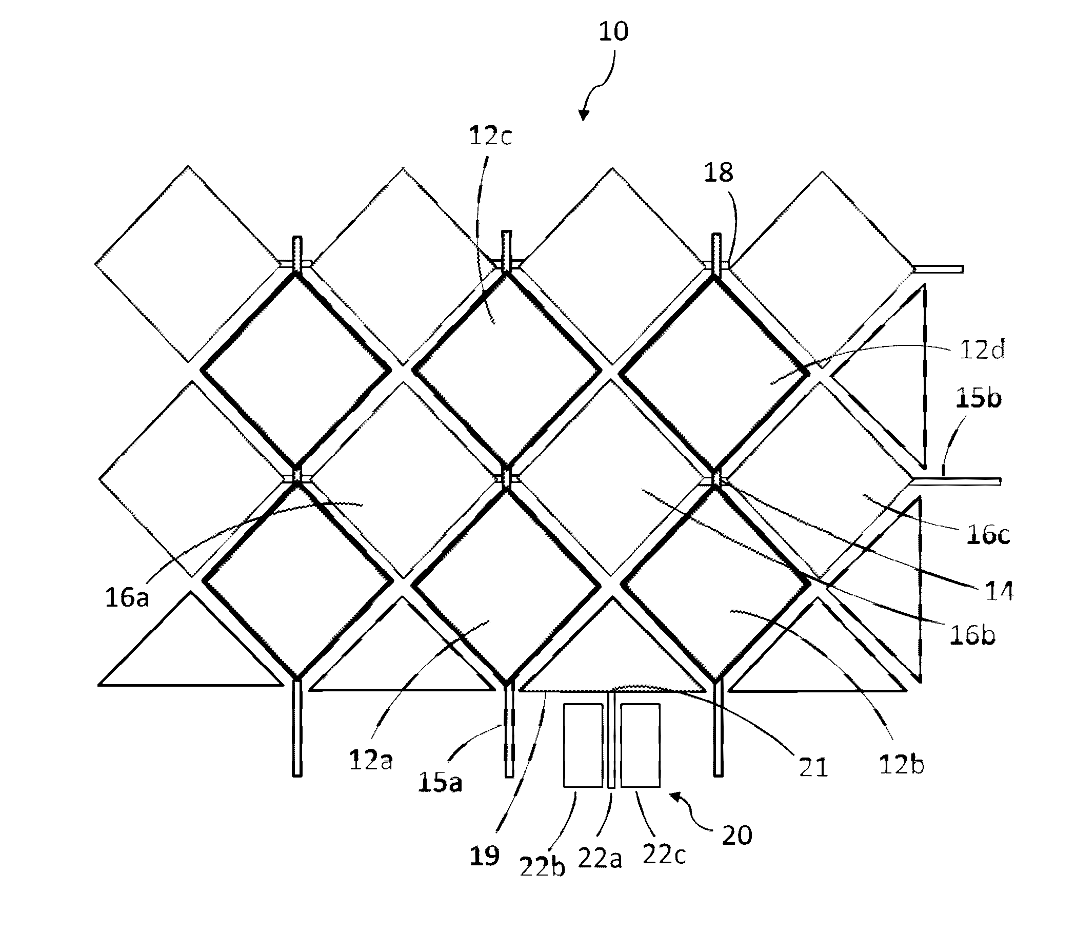
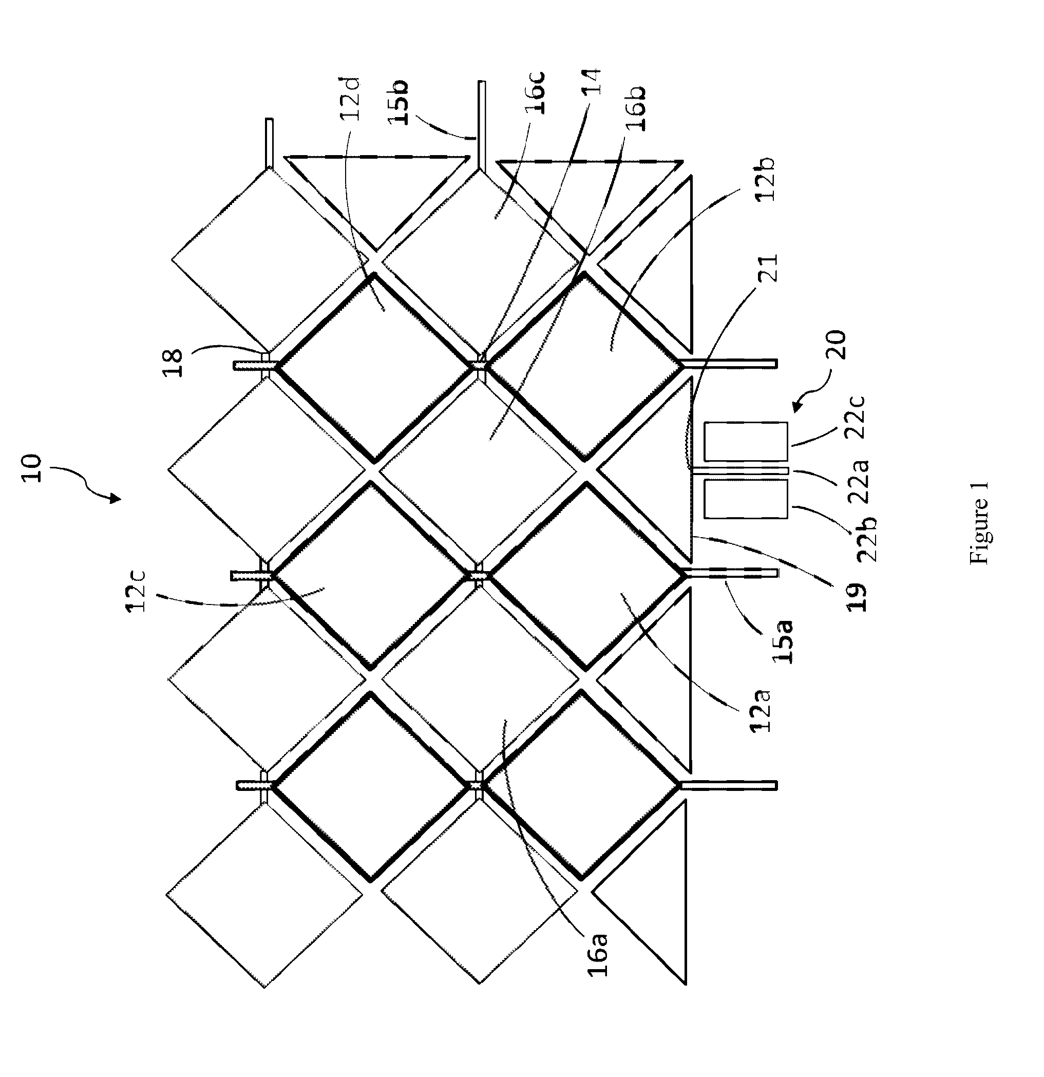
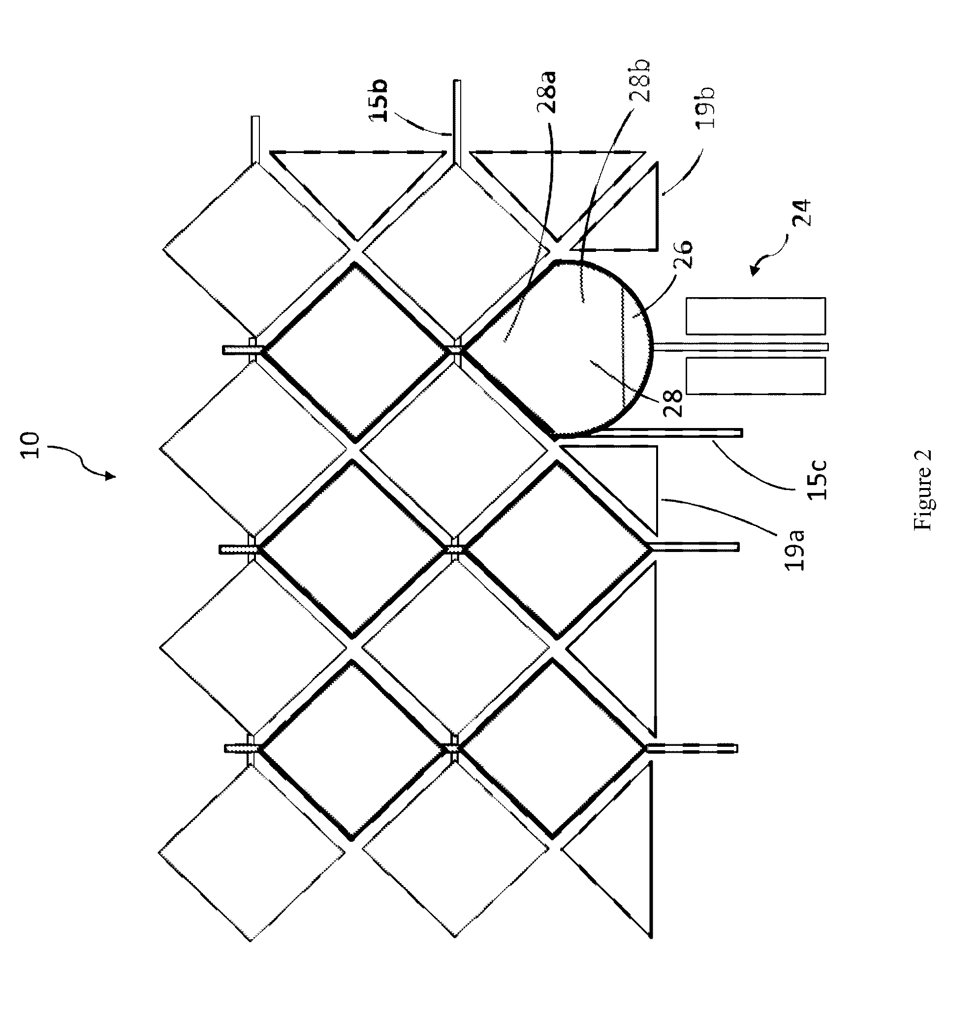
[0026]FIG. 1 shows a top view of an exemplary configuration of a touchscreen antenna system 10, integrated with a typical touchscreen having two layers of touch sensors or active touchscreen elements or electrodes, each sensor having a shape of a parallelogram. A first set of sensors 12a, 12b, 12c, and 12d are disposed on a first sub...


PUM


Abstract

Disclosed is a touchscreen antenna system and a method of designing a touchscreen antenna system. The system and method are operative to integrate an antenna with one or more touchscreen components to render a compact and effective system and to provide a more robust operation. The system is configured such that an antenna element, comprising a radiating component or an antenna feeding portion, is electromagnetically coupled to a touchscreen element, including a touch sensor, a touch sensor line, and other active or passive elements of a touchscreen module. Accordingly, the system is capable to mitigate adverse effects, when operating in an environment or under conditions that may affect other systems or be susceptible to being affected by other sources, by designing antenna and touchscreen elements as an integrated unit. Additionally, the system and method provide an enhanced antenna system performance by incorporating touchscreen elements as part of the antenna design.

Description

CROSS REFERENCE TO RELATED APPLICATION[0001]This application is based upon and claims priority from co-pending U.S. Provisional Patent Application Ser. No. 62 / 095,479 entitled “TOUCHSCREEN ANTENNA SYSTEM AND DESIGN METHOD THEREOF” filed with the U.S. Patent and Trademark Office on Dec. 22, 2014, by the inventors herein, the specification of which is incorporated herein by reference.FIELD OF THE INVENTION[0002]The present invention relates to antenna systems and methods. More particularly, the present invention relates to antenna systems and to antenna design and manufacturing methods for integrating antennas with touchscreen systems.BACKGROUND OF THE INVENTION[0003]A number of antenna designs and systems exist within various industries for enabling communications of a touchscreen module at several frequency bands for multiple applications. More specifically, nowadays touchscreen modules may require antennas for Wireless Fidelity (Wi-Fi), Bluetooth, Radio Frequency (RF) identificatio...

Claims


Application Information

Patent Timeline
IPC IPC(8): G06F3/041H01Q1/22G06F3/043G06F3/044G06F3/045
CPCG06F3/0416G06F3/044H01Q1/2258G06F3/043G06F3/0414G06F3/045G06F3/04182G06F3/0446G06F2203/04107H01Q1/44H01Q21/0075
Inventor SEBASTIAN, TOMBAYRAM, YAKUP
Owner PANERATECH
Learn More