
Camera calibration

a technology for calibration and cameras, applied in the field of camera calibration, can solve the problems of difficult to achieve a consistent level of calibration accuracy, untrained people will likely have trouble accurately calibrating cameras,

Active Publication Date: 2016-06-23
DISNEY ENTERPRISES INC
View PDF3 Cites 80 Cited by
  • Summary
  • Abstract
  • Description
  • Claims
  • Application Information

AI Technical Summary

Benefits of technology

This patent describes a calibration system that uses multiple light sources and a computing system to determine the location of objects in a 3D space and the properties of a camera used to capture images of those objects. This allows for accurate and precise calibration of the camera's position and orientation relative to the 3D space. The system can be used in a variety of applications, such as in virtual or augmented reality, to improve the accuracy of image-based interactions and experiences.

Problems solved by technology

Thus, an untrained person will likely have trouble accurately calibrating the camera with this method.
Moreover, it is often difficult to achieve a consistent level of calibration accuracy over a variety of calibrations being carried out by different people who may use different checkerboards that are arranged at different positions and orientations.

Method used


Image

  • Camera calibration
  • Camera calibration
  • Camera calibration

Examples


Embodiment Construction

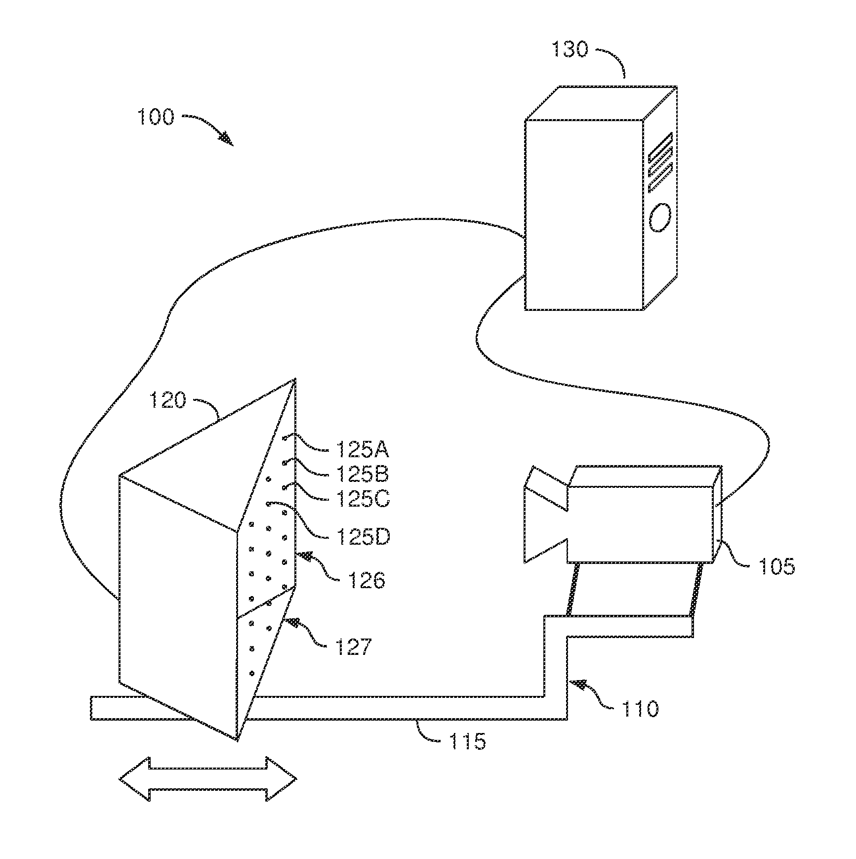
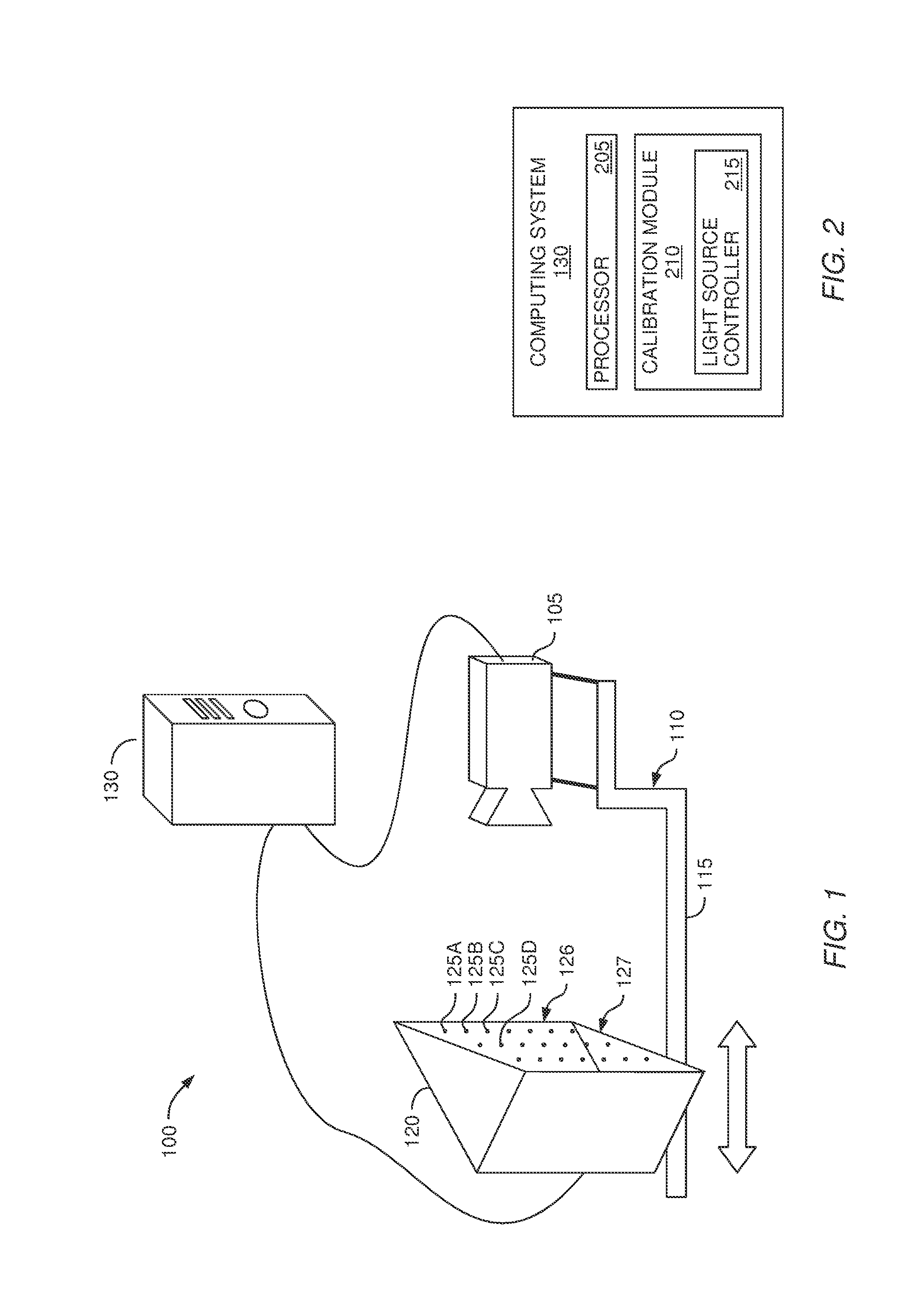
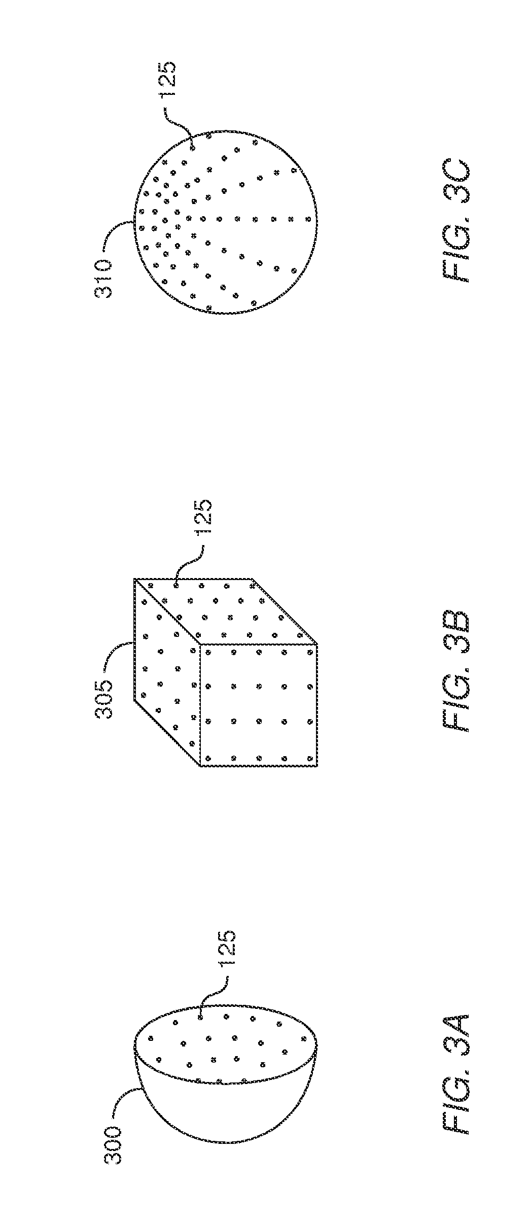
[0022]Embodiments described herein provide an automated system for measuring the intrinsics of a camera. The system includes a calibration apparatus which has a fixed spatial relationship relative to the camera. In one embodiment, once the calibration apparatus is moved into the field of view of the camera, the calibration is performed without the calibration apparatus having to be repositioned or reoriented whether by a human or mechanical means. The calibration apparatus includes a plurality of light sources (e.g., LEDs) which are controlled by a computing system. By selectively activating one or more of the light sources, the computing system determines the 2D location of the light sources in the images captured by the camera. Using this information, the computing system identifies correspondences that relate the known 3D positions of the light sources in space to the 2D locations in the image captured by the camera (referred to herein as 3D to 2D correspondences). The computer s...


PUM


Abstract

Embodiments herein include systems, methods and articles of manufacture for calibrating a camera. In one embodiment, a computing system may be coupled to a calibration apparatus and the camera to programmatically identify the intrinsic properties of the camera. The calibration apparatus includes a plurality of light sources which are controlled by the computer system. By selectively activating one or more of the light sources, the computer system identifies correspondences that relate the 3D position of the light sources to the 2D image captured by the camera. The computer system then calculates the intrinsics of the camera using the 3D to 2D correspondences. After the intrinsics are measured, cameras may be further calibrated to in order to identify 3D locations of objects within their field of view in a presentation area. Using passive markers in a presentation area, computing system may use an iterative process that estimates the actual pose of the camera.

Description

BACKGROUND[0001]1. Field of the Invention[0002]Embodiments presented in this disclosure generally relate to camera calibration and more specifically, to calculating the intrinsic characteristics and pose of a camera.[0003]2. Description of the Related Art[0004]Many applications require accurate camera calibration of the intrinsics of a camera—e.g., focal length, principal point, lens distortion parameters, and the like. A common way to identify the intrinsics of a camera is by using a checkerboard target that is captured from several different views using the camera. This method of calibration requires the checkerboard to be held at different ranges with different inclinations relative to the camera being calibrated. Thus, an untrained person will likely have trouble accurately calibrating the camera with this method. Moreover, it is often difficult to achieve a consistent level of calibration accuracy over a variety of calibrations being carried out by different people who may use ...

Claims


Application Information

Patent Timeline
IPC IPC(8): H04N17/00G06T7/00
CPCH04N17/002G06T7/0018G06T2207/30244G06T2207/30204G06T7/0044G06T7/80G06T7/74
Inventor GRUNDHOFER, ANSELM
Owner DISNEY ENTERPRISES INC
Learn More