
Bearing adapter side frame interface for a railway car truck

a technology for railway cars and bearing adapters, which is applied in the direction of axle boxes, railway components, bogies, etc., can solve the problems of increased wear on the track and equipment, lateral and longitudinal forces between the wheel and the rail, and dangerous hunting, so as to reduce the cold flow of low friction materials and reduce friction coefficients

Inactive Publication Date: 2016-06-23
STRATO AG
View PDF2 Cites 1 Cited by
  • Summary
  • Abstract
  • Description
  • Claims
  • Application Information

AI Technical Summary

Benefits of technology

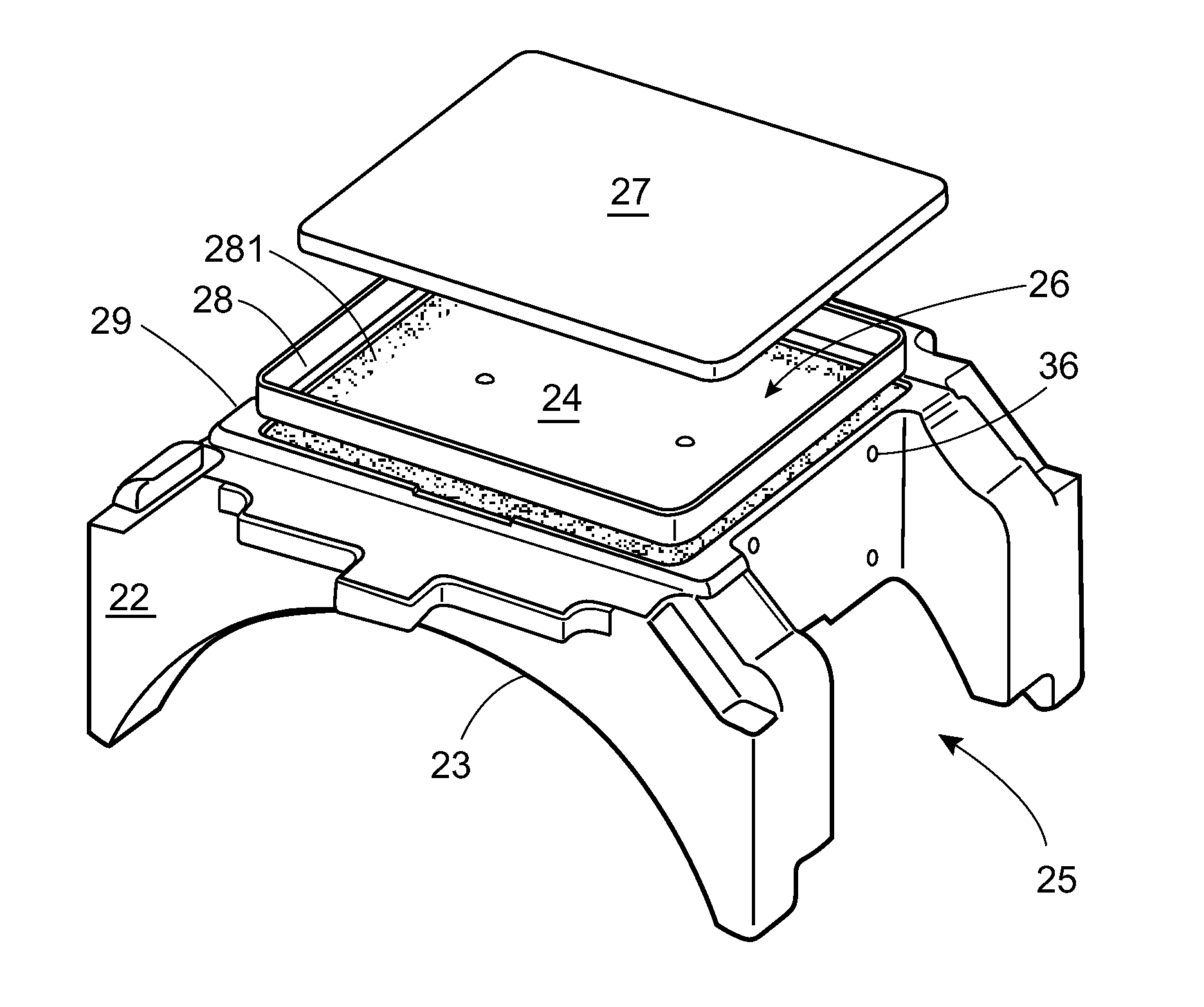
The invention is a new system that reduces friction between a bearing adapter and a pedestal jaw to prevent material deformation. It does not change the overall height of the truck and includes an adapter plate to align elastomeric members in the side frame / bearing adapter interface. This allows for a higher spring constant in the longitudinal direction. The invention also combines elastomeric pads in both the longitudinal and lateral directions with the adapter plate, resulting in fewer components to be installed.

Problems solved by technology

However, at high speeds, minor perturbations in the track or in the equipment can lead to a condition known as “hunting,” which describes an oscillating lateral movement of the wheel sets that causes the railcar to move side-to-side on the track.
Hunting may be dangerous when the oscillations attain a resonant frequency.
When a railway car truck encounters a turn, the distance traversed by the wheels on the outside of the curve is greater than the distance traversed by wheels on the inside of the curve, resulting in lateral and longitudinal forces between the wheel and the rail.
The “lozenging” condition can cause increased wear on the track and equipment, increase rolling resistance, and if severe enough result in a derailment.
However, the prior art disclosure relating to elastomeric pads fails to adequately provide a different spring rate in the longitudinal direction compared to the lateral direction.

Method used


Image

  • Bearing adapter side frame interface for a railway car truck
  • Bearing adapter side frame interface for a railway car truck
  • Bearing adapter side frame interface for a railway car truck

Examples


Embodiment Construction

[0021]Directions and orientations herein refer to the normal orientation of a railway car in use. Thus, unless the context clearly requires otherwise, the “longitudinal” axis or direction is parallel to the rails and in the direction of movement of the railway car on the track in either direction. The “transverse” or “lateral” axis or direction is in a horizontal plane perpendicular to the longitudinal axis and the rail. The term “inboard” means toward the center of the car, and may mean inboard in a longitudinal direction, a lateral direction, or both. Similarly, “outboard” means away from the center of the car. “Vertical” is the up-and-down direction, and “horizontal” is a plane parallel to the rails including the transverse and longitudinal axes. A truck is “square” when its wheels are aligned on parallel tracks and the axles are parallel to each other and perpendicular to the side frames. The “leading” side of the truck means the first side of a truck on a railway car to encount...


PUM


Abstract

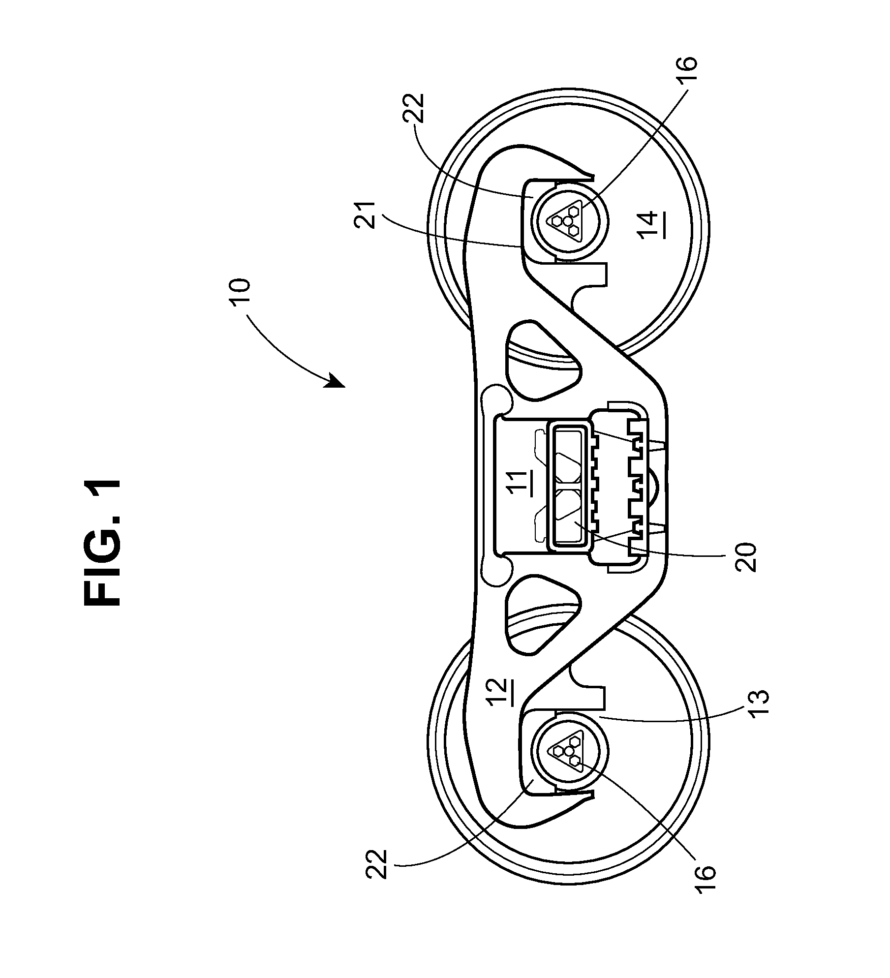
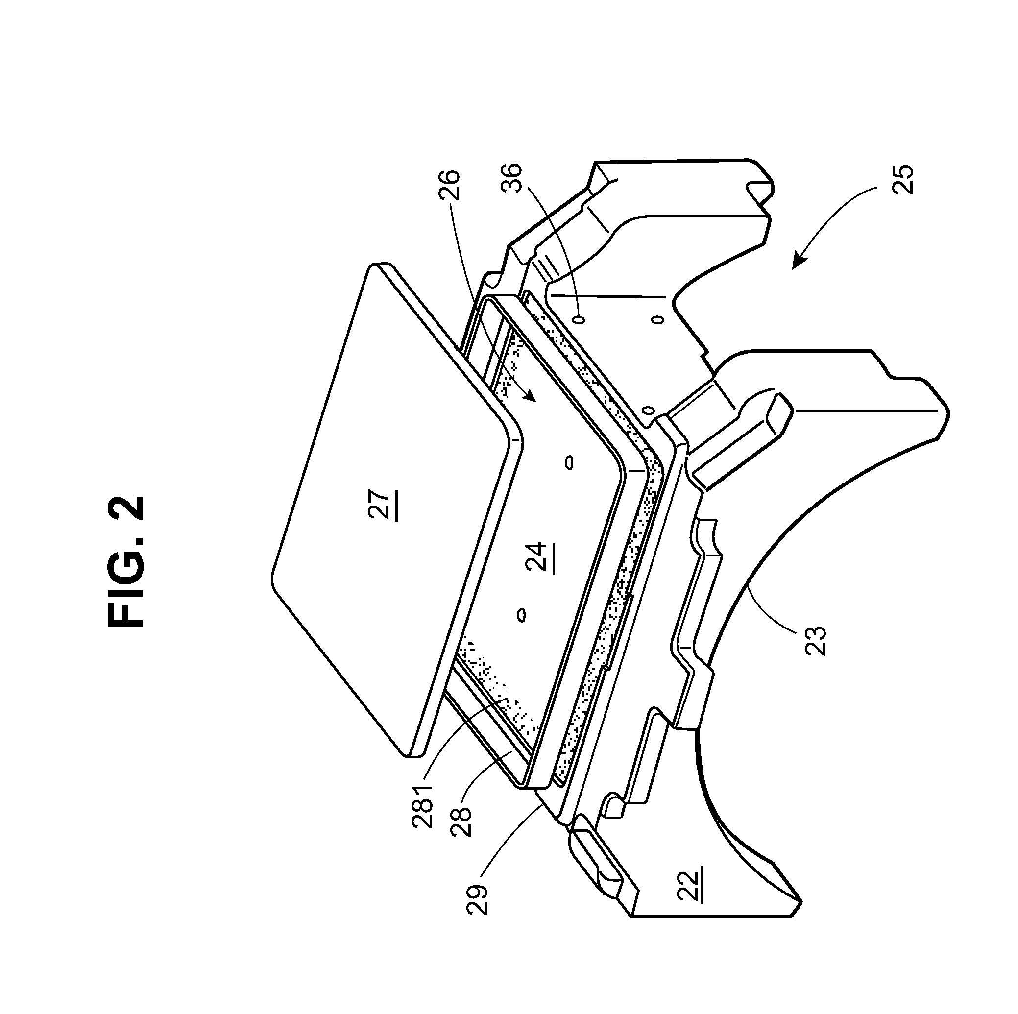
The invention relates to a railway car truck incorporating an interconnection between a side frame and a bearing adapter. The bearing adapter may receive a reduced coefficient of friction surface member in a recess on a top surface of the bearing adapter, facilitating a reduced lateral spring rate of the wheelset. Alternatively, or in combination, an adapter plate is received in the pedestal jaw on the bearing adapter to retain the reduced coefficient of friction surface member above or below the adapter plate. The adapter plate may be provided with surfaces about perpendicular to the longitudinal and lateral axes of the side frame to support elastomeric members, which may provide different longitudinal and lateral spring rates in response to a load applied to the truck.

Description

FIELD OF THE INVENTION[0001]The invention relates to an interface between a bearing adapter and a side frame in a railway car truck. Specifically, the invention relates to improvements in the bearing adapter which provide for the combination of a reduced friction surface member between the pedestal roof and the bearing adapter, and also to an adapter plate design that provides for an improved interface between the pedestal jaw and the bearing adapter.BACKGROUND OF THE INVENTION[0002]The conventional railway car truck in use in North America for several decades has been the three-piece truck, comprising a pair of parallel side frames oriented longitudinally connected by a transversely mounted bolster. The bolster is supported on the side frames by spring sets. The wheel sets of the truck are received in bearing adapters placed in leading and trailing pedestal jaws in the side frame, so that axles of the wheel sets are parallel. The bearing adapters permit slight angular adjustment of...

Claims


Application Information

Patent Timeline
Patent Type & Authority Applications(United States)
IPC IPC(8): B61F15/16B61F15/20
CPCB61F15/20B61F15/16B61F5/26B61F5/32B61F5/305
Inventor LIN, DAVID YUH-SHYANGHEYDEN, THOMAS J.BERG, THOMAS R.CLARK, CHRISTOPHER J.MCGARVEY, KEVIN P.
Owner STRATO AG
Learn More