Motor driver having integrated braking chopper

a technology of braking chopper and motor, which is applied in the direction of motor/generator/converter stopper, dynamo-electric converter control, dc motor stopper, etc., can solve the problems of higher construction cost, large physical size of motor, and higher construction cos

Active Publication Date: 2016-06-16
CATERPILLAR INC
View PDF0 Cites 2 Cited by
  • Summary
  • Abstract
  • Description
  • Claims
  • Application Information

AI Technical Summary

Problems solved by technology

However, such components usually cost more and have larger physical sizes.
As a result, the motor also requires a more expensive insulation system, and has a higher construction cost and larger physical size.

Method used


Image

  • Motor driver having integrated braking chopper
  • Motor driver having integrated braking chopper
  • Motor driver having integrated braking chopper

Examples


Embodiment Construction

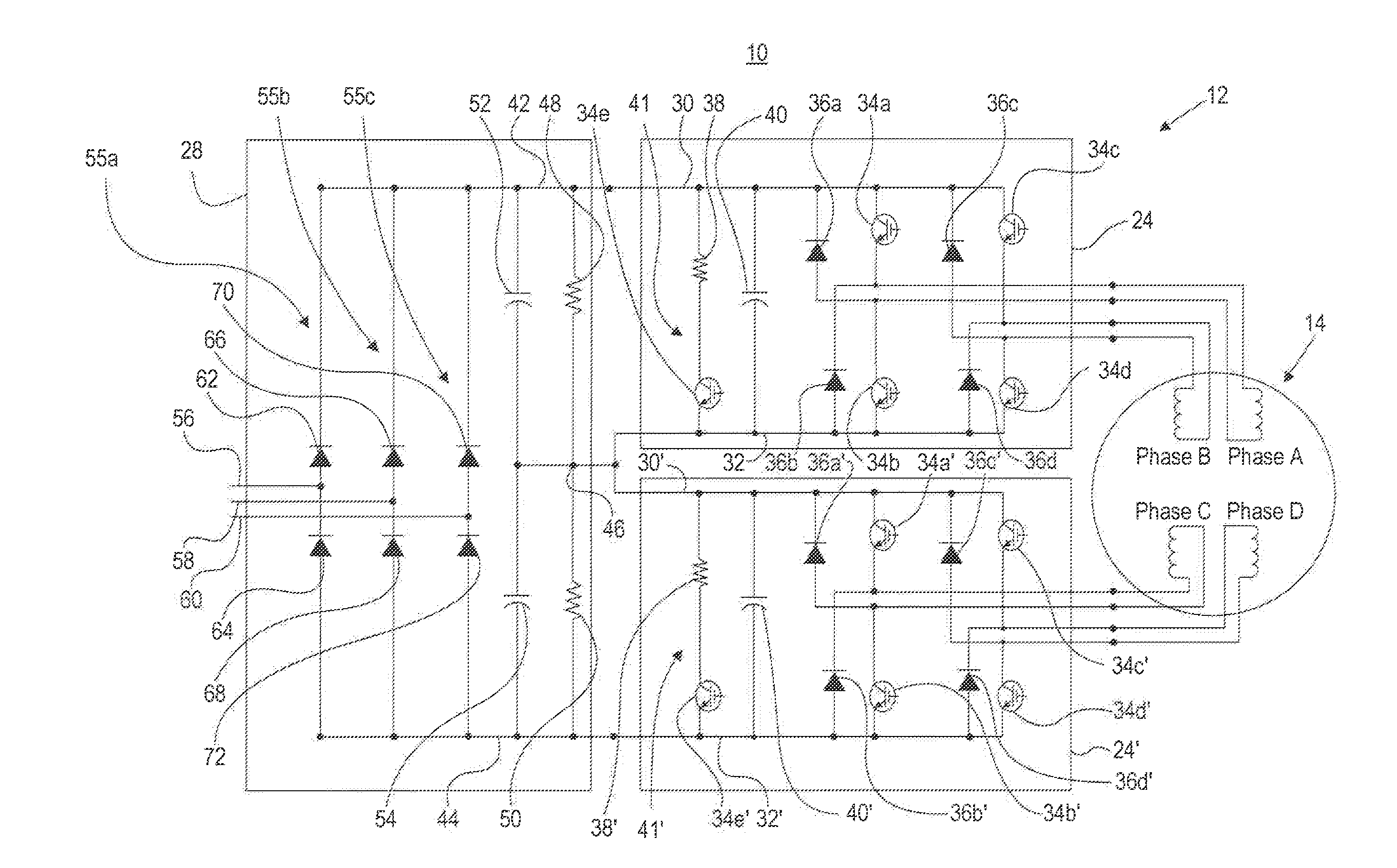
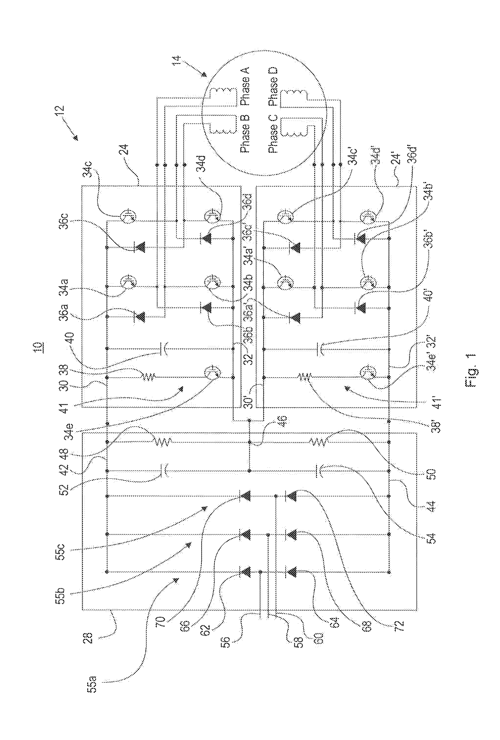
[0014]FIG. 1 illustrates an exemplary motor system 10 having a motor driver 12 and a motor 14. Motor system 10 may form a portion of a fixed or mobile machine that performs some type of operation associated with an industry such as mining, construction, farming, transportation, or any other industry known in the art. For example, motor system 10 may form a portion of an earth moving machine such as an excavator, a dozer, a loader, a backhoe, a motor grader, a dump truck, or any other earth moving machine. In motor system 10, motor driver 12 is configured to provide an electric power to motor 14.

[0015]Consistent with embodiments of the disclosure, motor 14 may be a switched reluctance (“SR”) motor, but can also embody another type of motor, provided the other type of motor has independently operated and electrically isolated phases. As one of ordinary skill in the art would understand, an SR motor has a plurality of magnetic poles mounted on a stator, which are grouped into two or mo...


PUM


Abstract

A motor driver for driving a motor is disclosed. The motor driver has a first power bus, a first switching device coupled between the first power bus and a first terminal of the motor, a second power bus, a second switching device coupled between the second power bus and a second terminal of the motor, and an integrated braking chopper coupled between the first and second power buses. The integrated braking chopper is configured to dissipate an extra power generated by the motor.

Description

TECHNICAL FIELD[0001]The present disclosure is related generally to a motor driver and, more particularly, to a motor driver having an integrated braking chopper.BACKGROUND[0002]A motor, such as a switched reluctance (SR) motor, is used to generate a mechanical power in response to an electrical input from a power source. Often times, the motor needs to be coupled to a power grid, such as a three-phase power grid, that provides electrical power to a large area. A motor system usually includes a motor driver that couples the motor to the power grid. The motor driver receives an input from the power grid and converts it to an electrical output that can be applied to the motor.[0003]Some applications require that the motor operate at a variable speed. In such scenarios, the motor driver may need to be able to handle a peak voltage from the power grid. Power grids in different areas may have different voltage levels, and some power grids may have a grid voltage (effective voltage) highe...

Claims


Application Information

Patent Timeline
Patent Type & Authority Applications(United States)
IPC IPC(8): H02P3/22H02P27/06
CPCH02P27/06H02P3/22H02P3/065
Inventor ADRA, RODWAN T.ZWILLING, EDWARD L.BAKER, THOMAS M.TATE, WILLIAM J.ANDRIS, ERIC M.
Owner CATERPILLAR INC
Why Eureka
Try Eureka