
Measuring device and method for measuring layer thicknesses and defects in a wafer stack

a technology of measuring device and wafer stack, which is applied in the direction of electrical/magnetic thickness measurement, semiconductor/solid-state device testing/measurement, instruments, etc., can solve the problems of total loss of individual bonded wafer stacks and catastrophic faults, and achieve the effect of decreasing thickness

Active Publication Date: 2016-06-16
EV GRP E THALLNER GMBH
View PDF11 Cites 8 Cited by
  • Summary
  • Abstract
  • Description
  • Claims
  • Application Information

AI Technical Summary

Benefits of technology

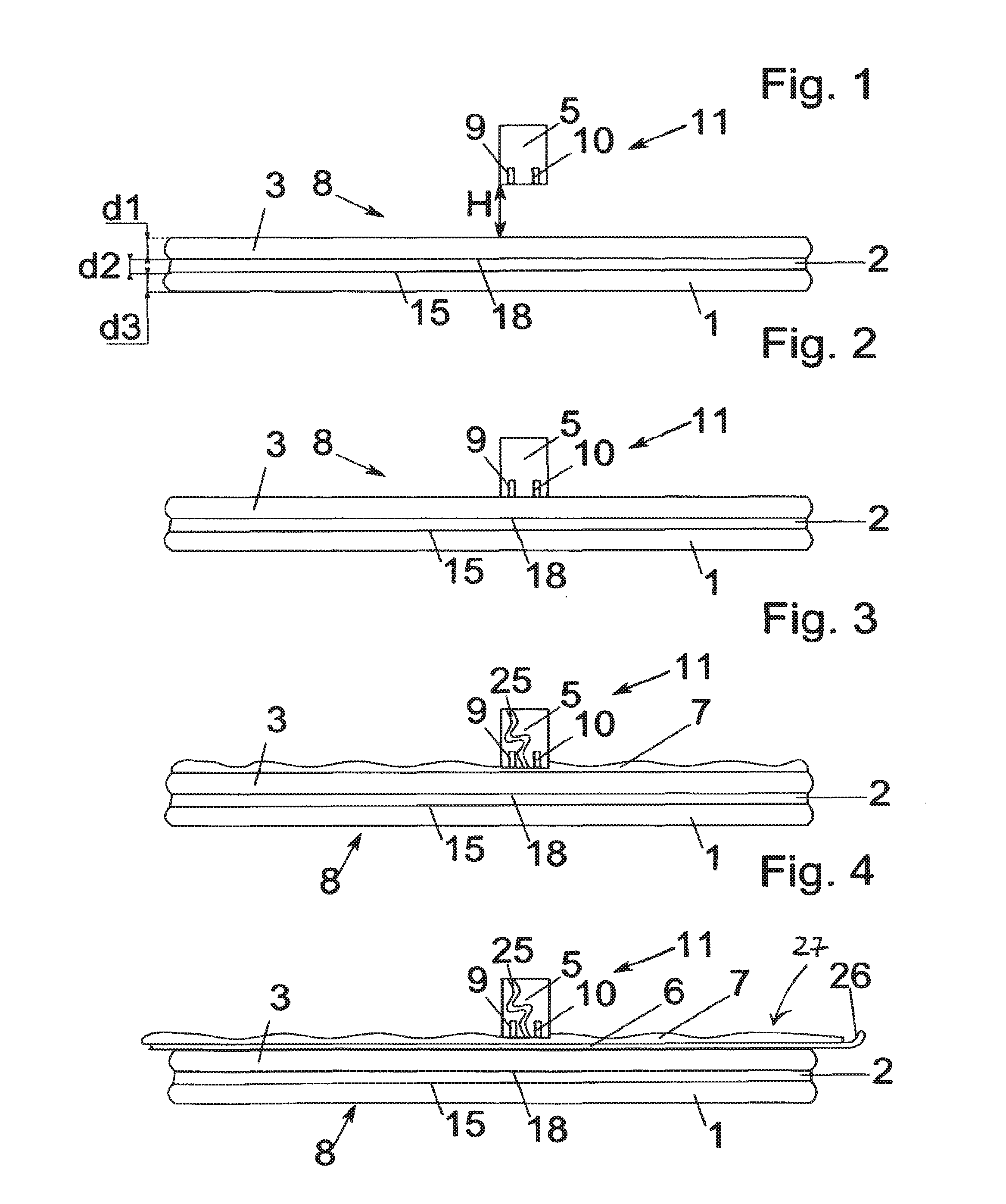
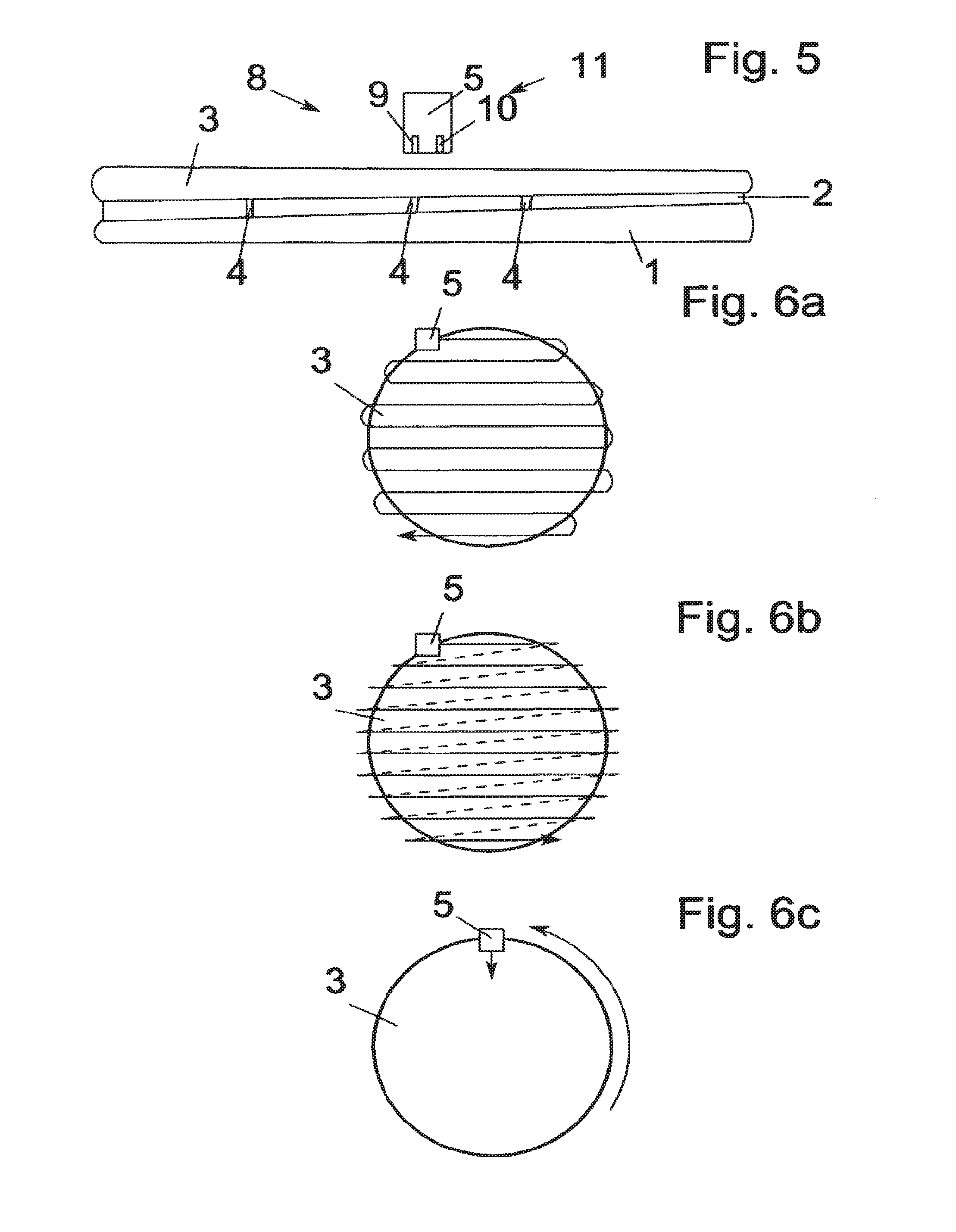
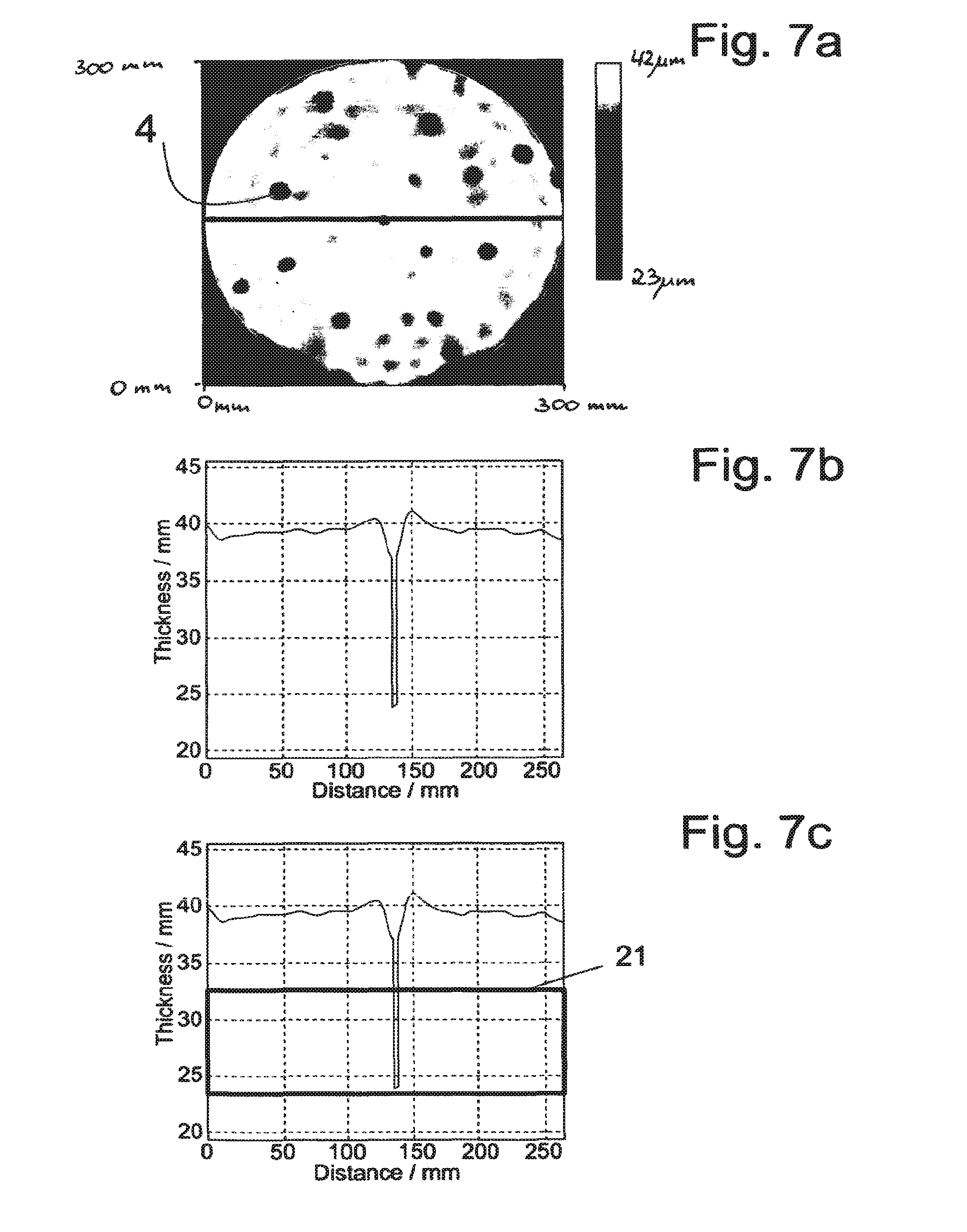
The invention aims to improve the quality criteria for temporarily bonded wafer stacks by optimizing adhesive quality and thickness consistency. It aims to reduce scrap and improve logistical efficiency by measuring and detecting faults close in time to the temporary bonding step. The invention can be integrated into temporary bonding devices and can automatically evaluate acquired values to make decisions about further processing or removal of the wafer from the process chain. The measurements can take place "in-line," which means that as many wafer stacks as possible can be analyzed without reducing the productivity rate of the processing device. The invention allows for blanket, grid-like sensing of the entire wafer stack to detect all voids as seamlessly as possible.

Problems solved by technology

As already stated, the grinding process constitutes an irreversible process which can lead to catastrophic faults and especially to a total loss of individual bonded wafer stacks.

Method used


Image

  • Measuring device and method for measuring layer thicknesses and defects in a wafer stack
  • Measuring device and method for measuring layer thicknesses and defects in a wafer stack
  • Measuring device and method for measuring layer thicknesses and defects in a wafer stack

Examples


Embodiment Construction

[0053]The same components and parts with the same action are identified with the same reference numbers in the figures.

[0054]FIG. 8 shows a wafer processing device as claimed in the invention for processing of a wafer stack 8. Wafer stack 8 is comprised of one structure wafer 1, one connecting layer 2 and one wafer 3. The structure wafer 1 at a transition 15 between the structure wafer 1 and the connecting layer 2 has contacts 14 which have been introduced into the surface of the structure wafer 1 and bumps 13 which project from the surface and which can consist of metal alloys. The structure wafer 1 can also be made without structures, in the same way as the wafer 3 can be made with structures.

[0055]The wafer stack 8 is fixed, its flat side opposite the surface of the structure wafer 1, on a surface 16 of a mount 12, here a chuck. Fixing takes place via vacuum paths 17 of the mount 12.

[0056]The connecting layer 2 is made as temporary adhesive and by means of the latter the structur...


PUM


Abstract

A method for measuring and / or acquiring layer thicknesses and voids of one or more layers of a temporary bonded wafer stack on a plurality of measuring points is provided. A sequence of the method includes an arrangement of a measurement means for measuring and / or acquiring the layer thicknesses and voids of the layers of the wafer stack at the measuring points relative to a flat side of the wafer stack. The sequence further includes an emission of signals in the form of electromagnetic waves by a transmitter of the measurement means, and a receiving the signals which have been reflected by the wafer stack by a receiver of the measurement means. The sequence also includes an evaluation of the signals which have been received by the receiver by an evaluation unit.

Description

RELATED APPLICATIONS[0001]This application is a continuation of U.S. application Ser. No. 13 / 883,777, filed May 7, 2013, which is a U.S. National Stage Application of International Application No. PCT / EP2010 / 06902, filed Nov. 12, 2010, said patent applications hereby fully incorporated herein by reference.FIELD OF THE INVENTION[0002]This invention relates to a measuring device for measuring layer thicknesses and / or detecting voids of one or more layers of a wafer stack on a plurality of measuring points which are distributed on the wafer stack. Furthermore this invention relates to a wafer processing device for processing a wafer stack and a method for measuring layer thicknesses and / or detecting voids of one or more layers of a wafer stack at a plurality of measuring points which are distributed on the wafer stack.BACKGROUND OF THE INVENTION[0003]Development in the semiconductor industry is currently in the direction of wafer bonding processes becoming increasingly important. Thus ...

Claims


Application Information

Patent Timeline
Patent Type & Authority Applications(United States)
IPC IPC(8): H01L21/66G01B11/06
CPCG01B11/0625H01L22/20G01B17/025G01N29/043G01N29/265G01N29/27G01N29/275H01L21/67253H01L22/12G01N21/9501G01N21/9505G01N2291/02854G01N2291/0289G01N2291/044G01N2291/0231G01N2291/2697H01L21/67288G01B11/2441G01B17/02G01N29/04G01N21/95G01B7/06
Inventor WIMPLINGER, MARKUS
Owner EV GRP E THALLNER GMBH
Learn More