Magnetic resonance imaging apparatus and magnetic resonance imaging method

a magnetic resonance imaging and magnetic resonance imaging technology, applied in the field of magnetic resonance imaging, can solve problems such as image quality degradation, and achieve the effect of high-quality images

Active Publication Date: 2016-06-16
FUJIFILM HEALTHCARE CORP
View PDF5 Cites 4 Cited by
  • Summary
  • Abstract
  • Description
  • Claims
  • Application Information

AI Technical Summary

Benefits of technology

[0013]Even in case of measuring with the radial sampling method, a high-quality image can be acquired.

Problems solved by technology

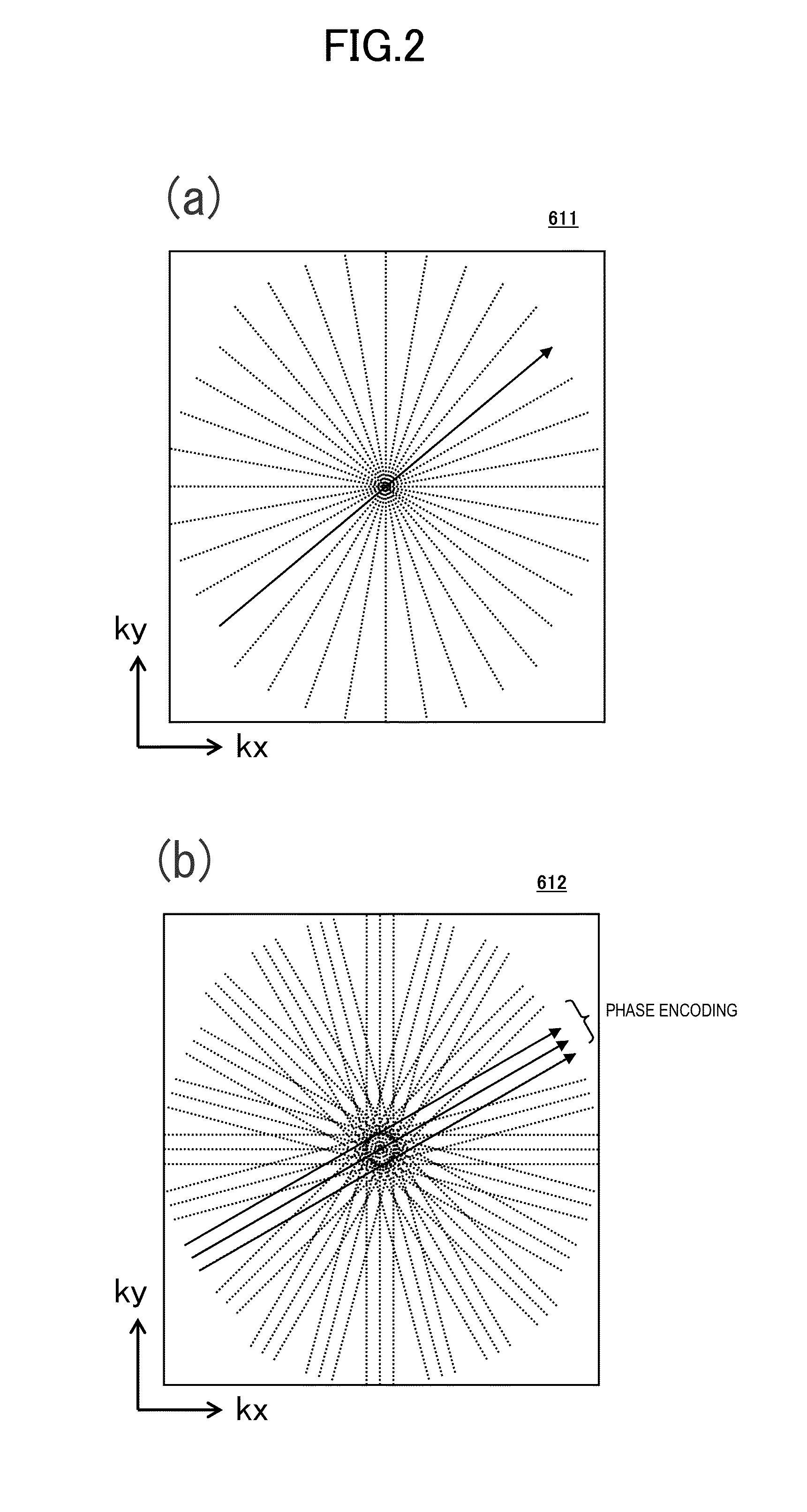
Since the blades at respective angles are intersected with each other and arranged in k-space in the radial sampling method, artifacts and uneven brightness are caused in case of an improper positional relationship between the blades, which results in image quality deterioration.

Method used


Image

  • Magnetic resonance imaging apparatus and magnetic resonance imaging method
  • Magnetic resonance imaging apparatus and magnetic resonance imaging method
  • Magnetic resonance imaging apparatus and magnetic resonance imaging method

Examples


first embodiment

[0026]Hereinafter, the embodiments of the present invention will be described using the attached diagrams. Additionally, in all the diagrams to describe the embodiments of the invention, unless otherwise stated, the same symbol is given to the same function, and the repeated explanation will be omitted.

[0027]

[0028]First, an example overview of the MRI apparatus related to the present invention will be described based on FIG. 1. FIG. 1 is a block diagram showing the overall configuration of an embodiment of the MRI apparatus related to the present invention.

[0029]The MRI apparatus 100 of the present embodiment acquires a tomographic image of an object using the NMR phenomenon and is provided with the static magnetic field generation system 120, the gradient magnetic field generation system 130, the high-frequency magnetic field generation system (hereinafter, referred to as “transmission system”) 150, the high-frequency magnetic field detection system (hereinafter, referred to as “re...

second embodiment

[0137]Next, the second embodiment to which the present invention is applied will be described. Although the first embodiment calculates shift amounts and corrected k-space coordinates for all the echoes in case of multi-echo measurement, the present embodiment calculates shift amounts and corrected k-space coordinates for minimally-required echoes to reduce an error measurement time in the multi-echo measurement.

[0138]In the present embodiment, the shift amount calculation is limited to once for echo signals whose shift amounts are almost the same in k-space during multi-echo measurement. This is particularly effective in the multi-echo measurement that has a number of echoes and is performed to visualize T2 and T2* values to be imaged.

[0139]The MRI apparatus of the present embodiment basically has a similar configuration to the MRI apparatus 100 of the first embodiment. Also, the overall imaging process flow is similar to the first embodiment. However, the configuration of the erro...


PUM


Abstract

The present invention obtains high-quality images even in a case of measurement with a radial sampling method. For this purpose, pre-measurement is performed to extract only a component different for each blade from among shift amounts from among echo signals, and a shift amount in k-space of an echo signal by the said component is reflected to a reconstruction process. In the pre-measurement, echo signals are obtained respectively by applying readout gradient magnetic field pulses that change the polarity to the positive and negative and that have the same pulse shape as readout gradient magnetic field pulses to be used in an image acquisition sequence. A shift amount is obtained for each axis of X, Y, and Z of an MRI apparatus as a variation amount of a phase difference between both the echo signals.

Description

TECHNICAL FIELD[0001]The present invention relates to a magnetic resonance imaging (hereinafter, referred to as “MRI”) apparatus that measures a nuclear magnetic resonance signal (hereinafter, referred to as “NMR signal”) from hydrogen, phosphorus, and the like of an object and images nuclear density distribution, relaxation time, and the like, and in particular to an imaging technique using a radial sequence that samples k-space radially.BACKGROUND ART[0002]The MRI apparatus is an apparatus that measures an NMR signal generated by atomic nucleus spin comprising tissue of an object, in particular human body and two-dimensionally or three-dimensionally images shapes and functions of the head, abdomen, extremities, and the like. In imaging, an object is disposed in a static magnetic field (a polarizing magnetic field B0), a high-frequency magnetic field pulse is applied together with a slice-selective gradient magnetic field pulse in order to selectively excite a certain region, and t...

Claims


Application Information

Patent Timeline
Patent Type & Authority Applications(United States)
IPC IPC(8): G01R33/565G01R33/36G01R33/48G01R33/385
CPCG01R33/56509G01R33/4818G01R33/36G01R33/385G01R33/4824G01R33/5617G01R33/482G01R33/565G01R33/56563
Inventor HANADA, HIKARUTAKAHASHI, MIYUKIOKA, KUNIHARUTAKIZAWA, MASAHIRO
Owner FUJIFILM HEALTHCARE CORP
Why Eureka
Try Eureka