
Hydraulic damping cylinder, in particular for a knee prosthesis

Active Publication Date: 2016-06-16
OSSUR ICELAND EHF
View PDF6 Cites 4 Cited by
  • Summary
  • Abstract
  • Description
  • Claims
  • Application Information

AI Technical Summary

Benefits of technology

The patent is about a device that helps individuals with prostheses move faster and more easily. The device uses a throttle valve to control the flow of hydraulic fluid, which in turn controls the movement of the prosthetic device. When the device moves quickly, the throttle valve increases the resistance to the fluid, causing the fluid to flow preferentially into a small chamber, which compresses the fluid and stores energy to assist in the movement. The device also includes an adjustment throttle valve that can be adjusted to control the flow of the fluid and a fixed position to prevent the valve from being completely closed. Overall, the device helps people with prostheses move more confidently and comfortably.

Problems solved by technology

Consequently, if a pressure builds up in the receiving chamber owing to the inflowing, virtually incompressible hydraulic fluid, normally an oil, a deformation of the diaphragm occurs, thus inevitably resulting in a decrease in volume of the compression chamber, which in turn leads to a compression of the fluid, for example air, contained in the compression chamber.

Method used


Image

  • Hydraulic damping cylinder, in particular for a knee prosthesis
  • Hydraulic damping cylinder, in particular for a knee prosthesis
  • Hydraulic damping cylinder, in particular for a knee prosthesis

Examples


Embodiment Construction

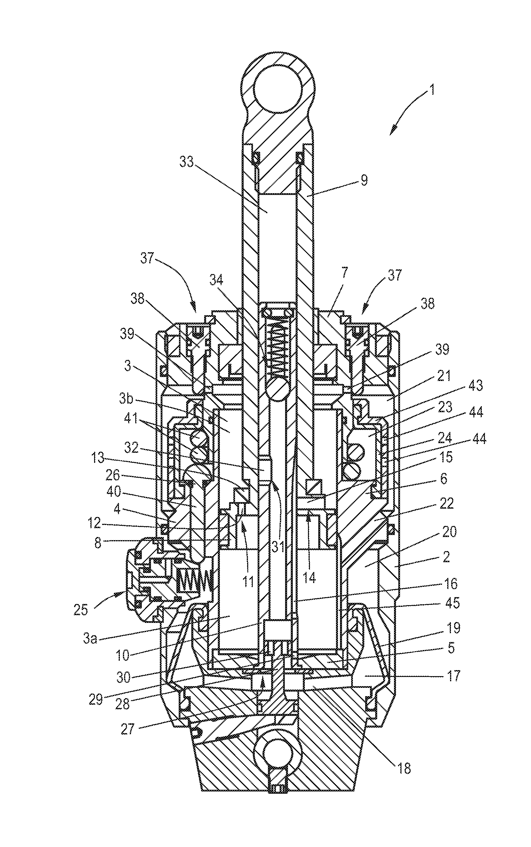
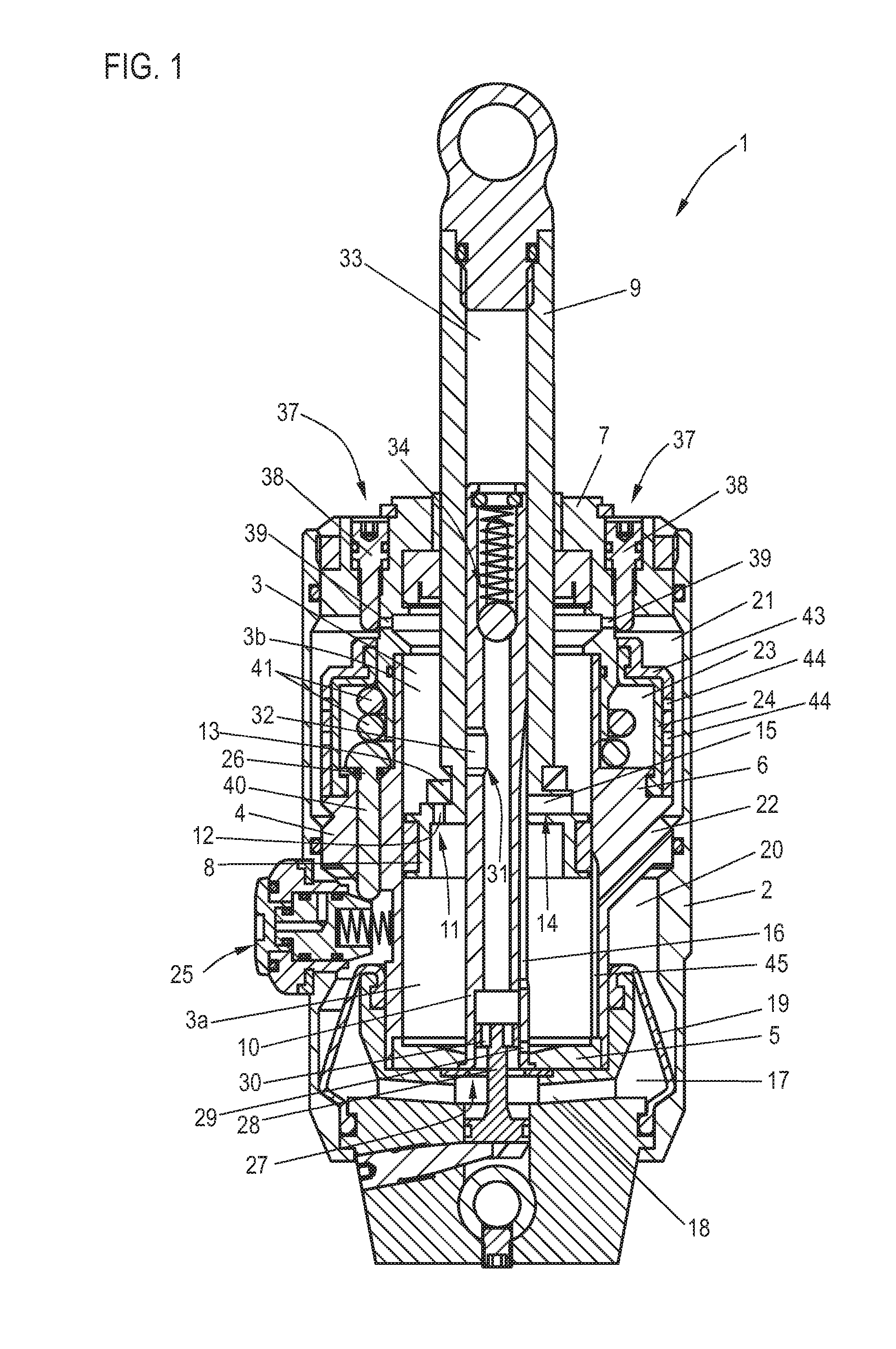
[0044]FIG. 1 shows a hydraulic damping cylinder 1 according to the invention which is suitable for a prosthetic knee joint. Said hydraulic damping cylinder comprises a housing 2, in the interior of which there is arranged an insert component 4 which has a cylinder chamber 3. The insert component 4 is of multi-part form and comprises a cylinder base 5 and a component body 6 which radially closes off the cylinder chamber 3. At the top side, the cylinder chamber 3 is closed by way of a cylinder cover element 7 which is fixed to the housing.

[0045]In the interior of the cylinder chamber 3 there is provided a piston 8 which is connected to a piston rod. The piston 8 and the piston rod 9 run or engage around a stanchion 10 which is fastened to the cylinder base 5. The piston 10 divides the cylinder chamber 3 into a lower cylinder chamber part 3a and an upper cylinder chamber part 3b. On the piston and on the piston rod there is provided a check valve 11, which is realized by way of a bore ...


PUM


Abstract

A hydraulic damping cylinder for a prosthetic knee joint, including a housing, a cylinder chamber in the housing and filled with a hydraulic fluid, and a piston arranged in the cylinder chamber and movable by a piston rod. In the housing there are provided at least two separate receiving chambers, which are of different size and are connected to the cylinder chamber by fluid ducts, for hydraulic fluid displaced from the cylinder chamber during a piston movement. The receiving chambers are each separated, by a diaphragm, from a compression chamber filled with a compressible fluid that forms an energy store. Upstream of the larger receiving chamber, there is connected a throttle device which forms a flow resistance for the hydraulic fluid flowing into the receiving chamber so that the hydraulic fluid can be distributed to the two receiving chambers in a manner dependent on speed of the piston movement.

Description

CROSS-REFERENCE TO RELATED APPLICATIONS[0001]The present application claims priority of DE 10 2014 018 712.8, filed Dec. 16, 2014 and DE 10 2015 100 876.9, filed Jan. 21, 2015, the priority of these applications is hereby claimed and these applications are incorporated herein by reference.BACKGROUND OF THE INVENTION[0002]The invention relates to a hydraulic damping cylinder, in particular for a prosthetic knee joint, comprising a housing, a cylinder chamber which is provided in the housing and which is filled with a hydraulic fluid, and a piston which is arranged in said cylinder chamber and which can be moved in the cylinder chamber by way of a piston rod which is introduced into the cylinder chamber.[0003]A hydraulic damping cylinder of said type is used for example in a prosthetic knee joint in order to dampen the flexion movement during which the prosthetic knee joint bends, similarly to the human joint. Said damping is realized in purely fluid mechanical fashion by virtue of th...

Claims


Application Information

Patent Timeline
IPC IPC(8): A61F2/68A61F2/64F16F9/512F16F9/19F16F9/34
CPCA61F2/68F16F9/19F16F9/34A61F2002/745A61F2/64A61F2002/5006A61F2002/5038F16F9/5126F16F9/062F16F9/446
Inventor DRESSLER, JANEKKAMM, THOMASZOBIREI, SORENTSCHUPP, GABRIEL
Owner OSSUR ICELAND EHF
Learn More