Insulation Material as well as Insulation Element for a Pipe in the Vicinity of a Wall or Ceiling Duct
- Summary
- Abstract
- Description
- Claims
- Application Information
AI Technical Summary
Benefits of technology
Problems solved by technology
Method used
Image

Examples
Example
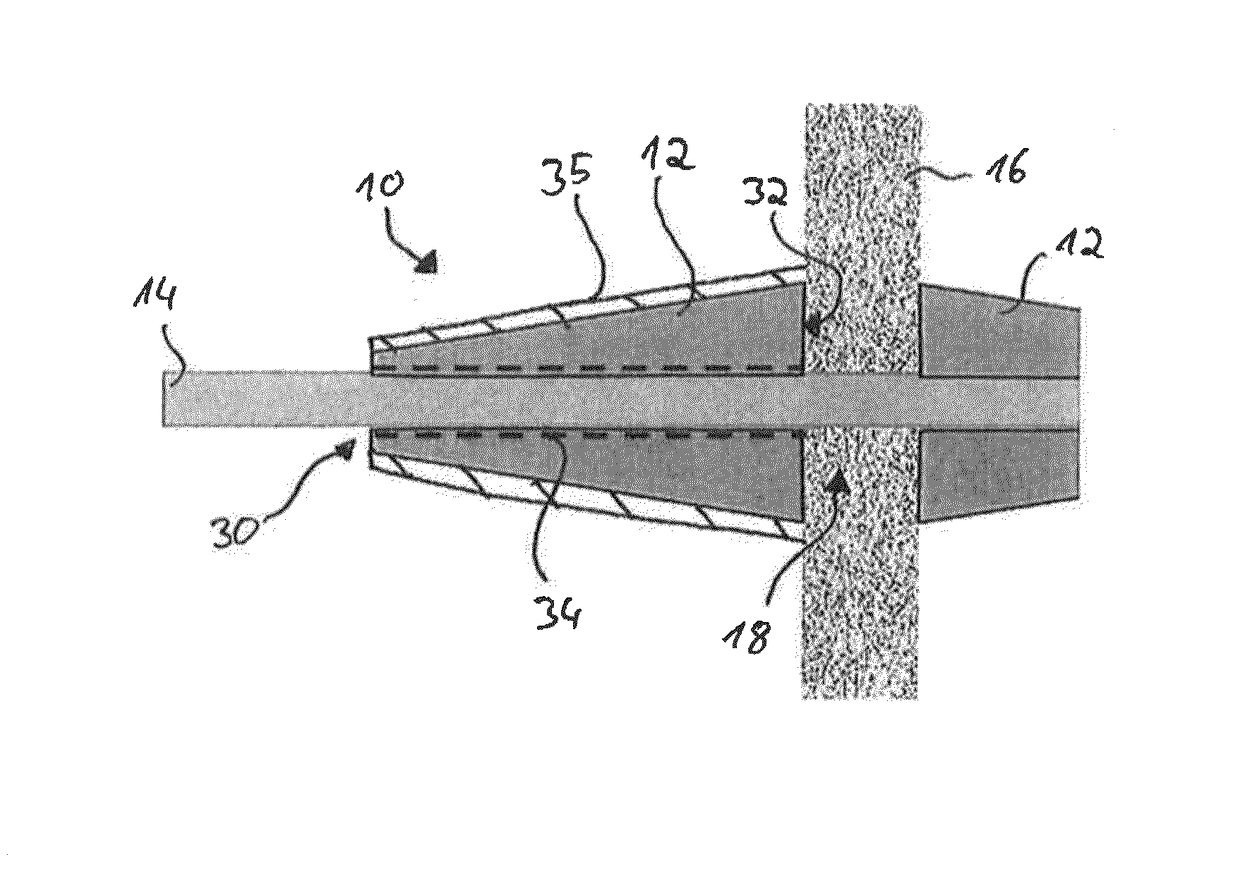
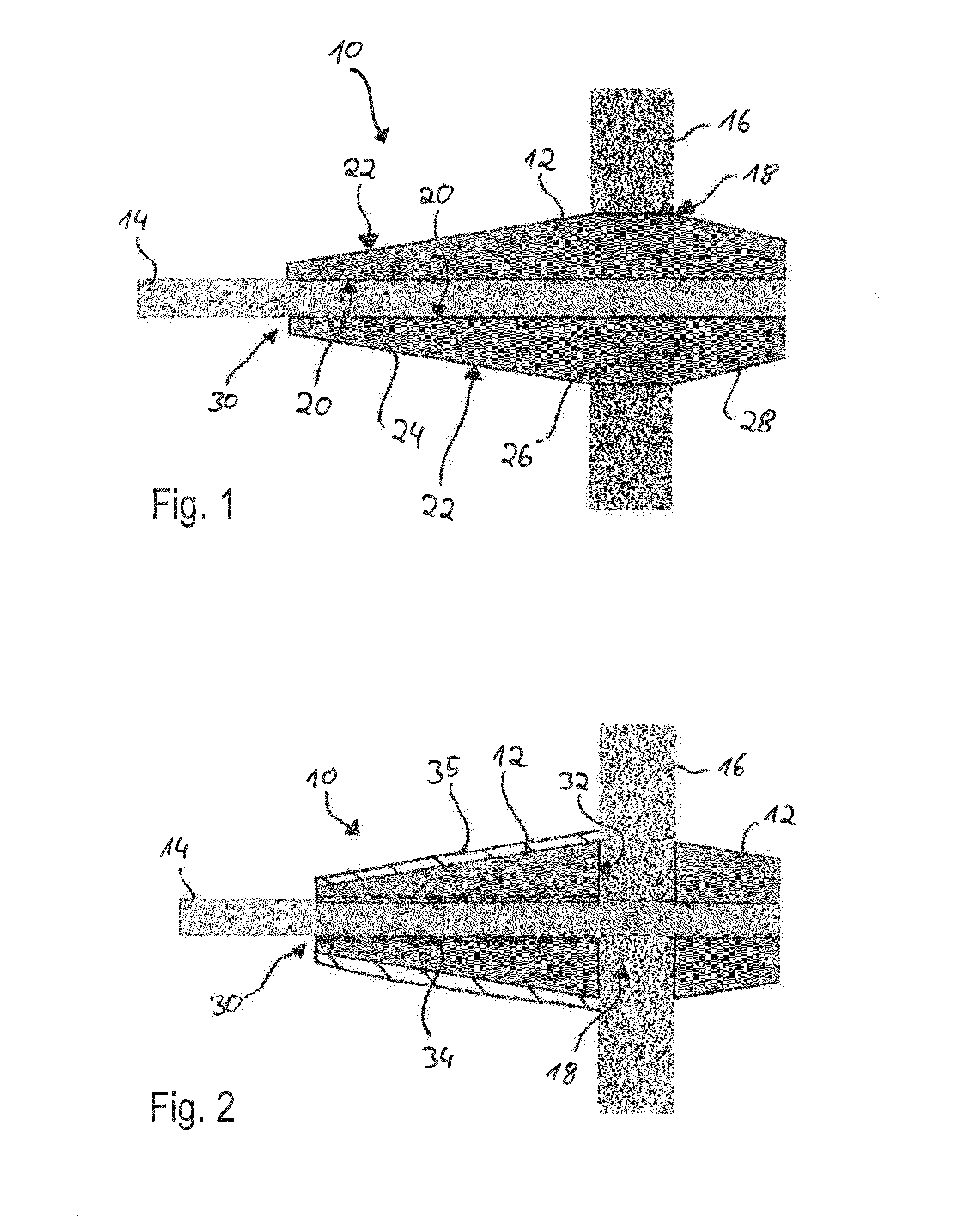
[0042]FIG. 2 depicts a second embodiment of insulation element 10, wherein insulation element 10 has an insulation material 12, which in contrast to the first embodiment is not run through wall duct 18, but whose contact surface 32 contacts wall 16.
[0043]Insulation material 12 of the second embodiment from FIG. 2 corresponds approximately to first section 24 of insulation material 12 of the first embodiment from FIG. 1. Insulation material 12, of the second embodiment according to FIG. 2, wrapped around pipe 14 is formed in a frusto-conical shaped manner, wherein the exterior circumference of the insulation material 12 is greatest in the vicinity of wall 16 or in contact surface 32. A wedge-shaped cross-section results over the entire axial expansion of the non-wrapped insulation material 12.
[0044]Insulation element 10 according to the second embodiment as depicted in FIG. 2 has two insulation materials 12, which are each arranged on both sides of wall 16, wherein insulation materia...
Example
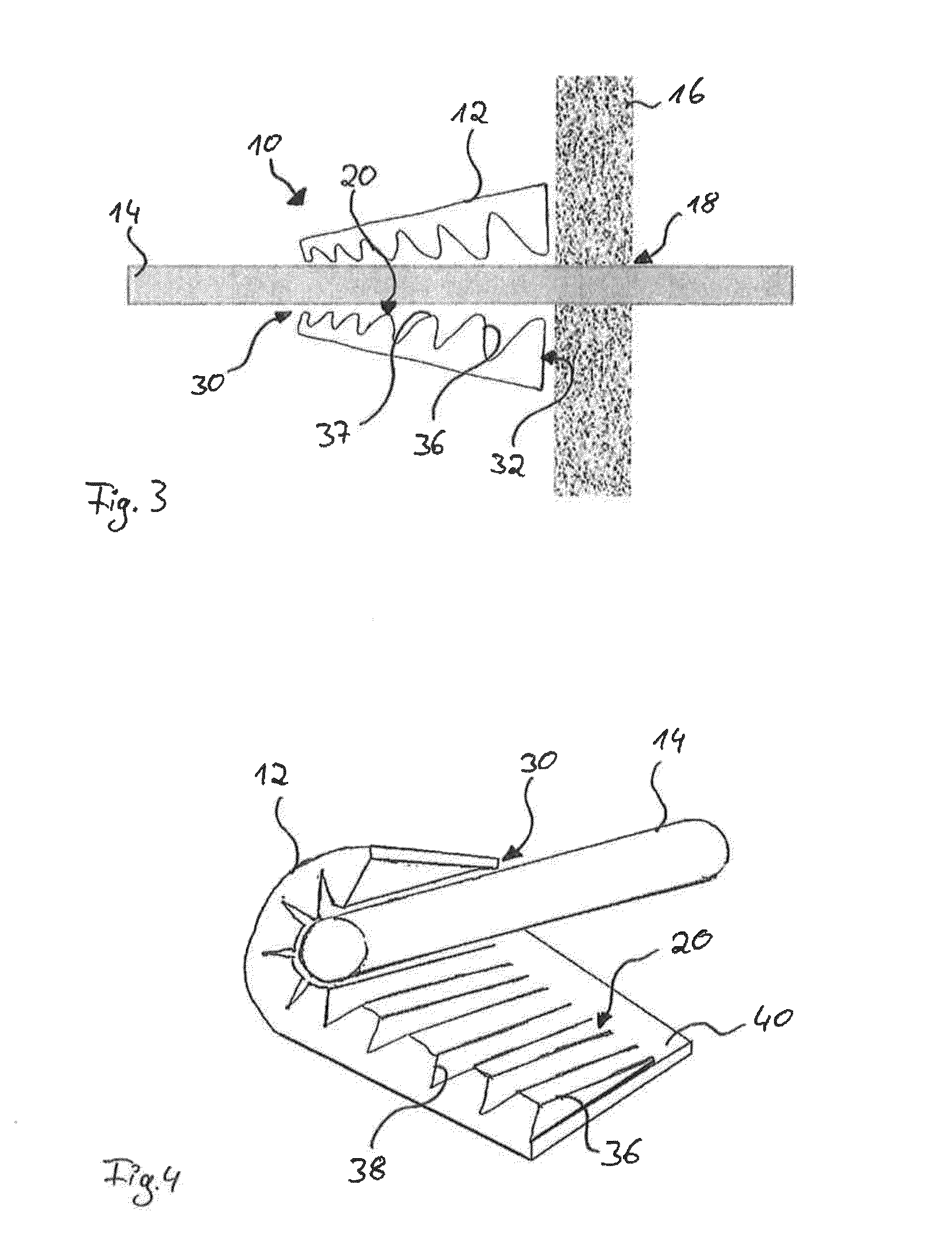
[0049]FIG. 3 depicts a third embodiment of insulation element 10, wherein the third embodiment differs from the second embodiment to the effect that interior surface 20 does not always contact pipe 14, but has a structuring 36.
[0050]In the depicted embodiment, structuring 36 is formed by nubs 37, whereby insulation material 12 contacts pipe 14 only via the nub tips of structuring 36.
[0051]Insulation material 12 is nonetheless designed to be wedge-shaped in its cross-section, so that the exterior circumference of wrapped insulation material 12 tapers toward free end 30, wherein the exterior circumference of insulation material 12 is in turn the greatest in the vicinity of wall 16 or contact surface 32.
[0052]Nubs 37 may in particular have various depths,
[0053]Such an insulation material 12 may be produced for example in such a manner that a normal convoluted foam is produced, whose nub depths differ, wherein a diagonal cut occurs, so that, in a cross-section, wedge-shaped insulation m...
Example
[0054]FIG. 4 depicts a fourth embodiment of insulation element 10, which, like the third embodiment according to FIG. 3, also has a structuring 36 on interior surface 20.
[0055]Structuring 36 in the fourth embodiment consists of conically shaped ribs 38, which run in a wedge-shaped manner in the cross-section and contact these when wrapping pipe 14. By means of conical wedge ribs 38, it is possible to wrap insulation material 12 around pipe 14 in a simple manner.
[0056]Insulation material 12 according to the fourth embodiment has, in addition to ribs 38, a rib-free contact region 40.
[0057]When wrapping pipe 14, insulation material 12 over interior surface 20 lies on pipe 14 in such a manner that ribs 38 are arranged toward wall 16, so that the exterior circumference of insulation material 12 is greatest there. Toward the free end 30, the diameter of insulation material 12 tapers due to the conically shaped wedge ribs 38, wherein wedge ribs 38 transition into contact region 40, which l...
PUM
 Abstract
Description
Claims
Application Information
 - R&D
- Intellectual Property
- Life Sciences
- Materials
- Tech Scout
- Unparalleled Data Quality
- Higher Quality Content
- 60% Fewer Hallucinations
Browse by: Latest US Patents, China's latest patents, Technical Efficacy Thesaurus, Application Domain, Technology Topic, Popular Technical Reports.
© 2025 PatSnap. All rights reserved.Legal|Privacy policy|Modern Slavery Act Transparency Statement|Sitemap|About US| Contact US: help@patsnap.com