
Vascular Clamp for Use in Minimally Invasive Surgery

a vascular clamp and minimally invasive technology, applied in the field of vascular clamps, can solve the problems of increasing the difficulty of surgical procedures on patients with obesity or intestinal adhesion problems, and achieve the effect of improving the efficiency of minimally invasive surgery and shortening the time for clamping

Inactive Publication Date: 2016-06-02
METAL INDS RES & DEV CENT
View PDF2 Cites 1 Cited by
  • Summary
  • Abstract
  • Description
  • Claims
  • Application Information

AI Technical Summary

Benefits of technology

The present invention is a vascular clamp designed for minimally invasive surgery. The clamp can be used with blood vessels of various diameters and is easy to clamp and unclamp. The design includes engagement blocks that can be quickly engaged in positioning holes to form a circled space suitable for blood vessels of various diameters, reducing the time required for surgical procedures. The clamp is reinforced to prevent deformation and disengagement of the engagement blocks. Overall, the clamp improves operational efficiency and reduces the postoperative recovery period of the patient.

Problems solved by technology

However, the surgical operator has a small field of vision during the surgery, and the surgical device has a small operating area, leading to an increase in the difficulties in the use of the surgical device.
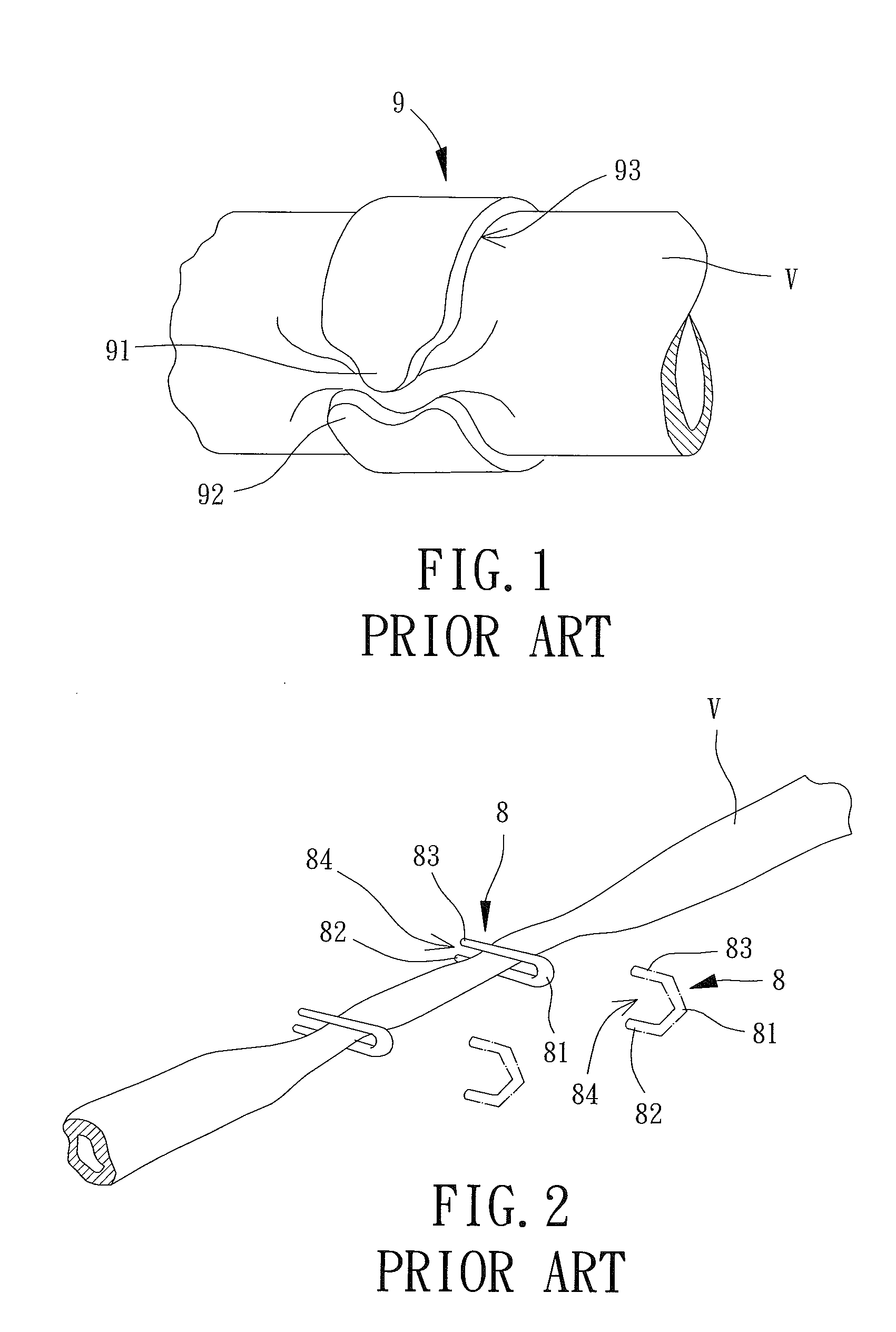
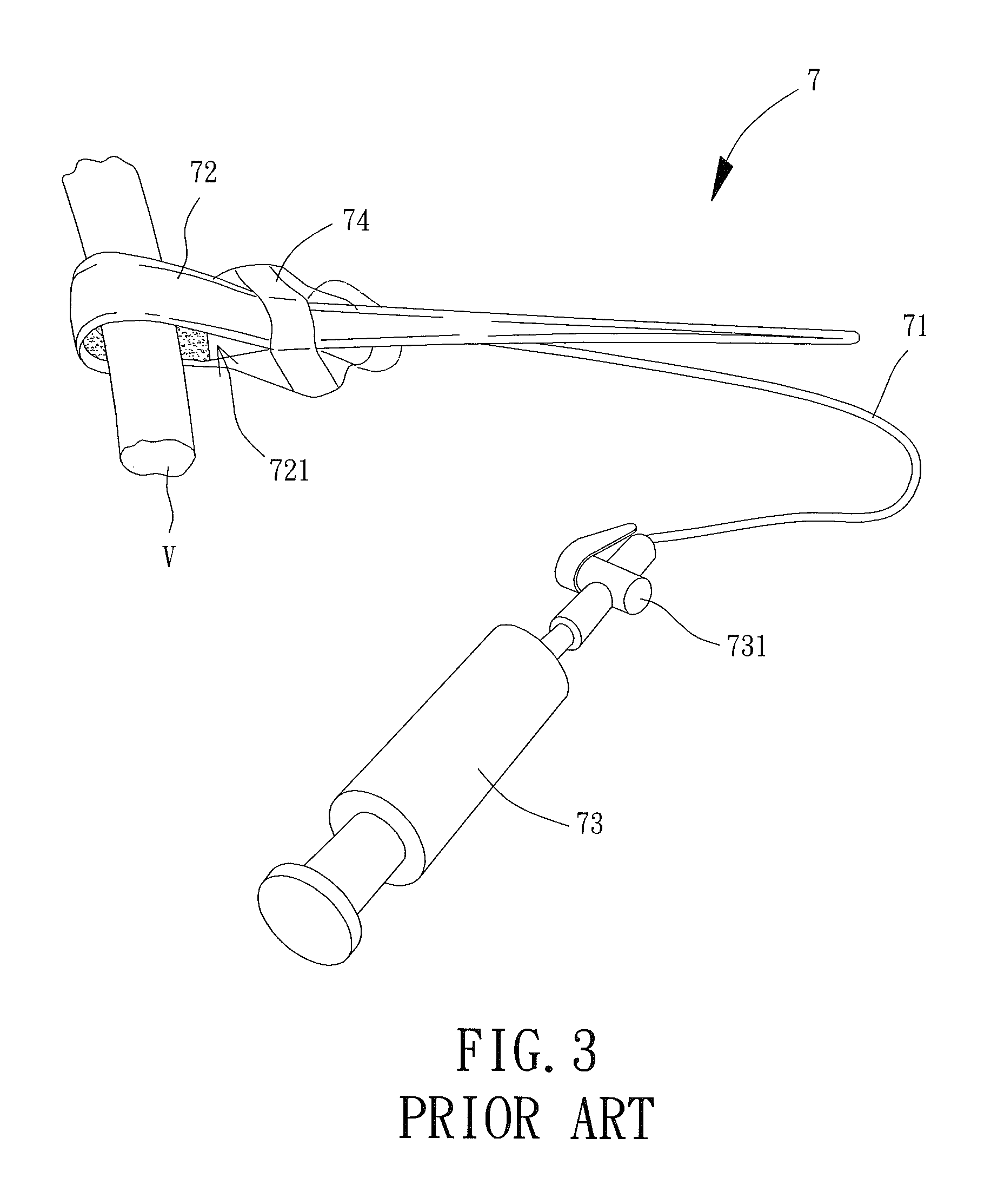
Thus, the surgical operator must spend extra time to remove the conventional vascular clamp 9 or the conventional hemoclip 8 during the surgical procedure, which not only extends the surgical procedure but results in difficulties in a surgical procedure on a patient with problems of obesity or intestinal adhesions.

Method used


Image

  • Vascular Clamp for Use in Minimally Invasive Surgery
  • Vascular Clamp for Use in Minimally Invasive Surgery
  • Vascular Clamp for Use in Minimally Invasive Surgery

Examples


Embodiment Construction

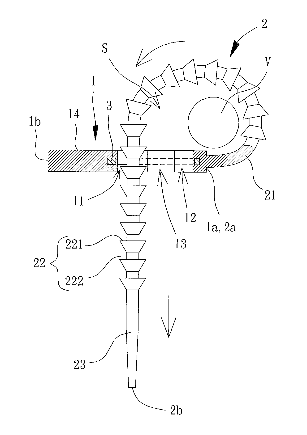
[0035]With reference to FIGS. 4-6, a vascular clamp for use in minimally invasive surgery of an embodiment according to the present invention includes a positioning member 1, a looping / tightening member 2, and a reinforcing member 3. The looping / tightening member 2 can extend through the positioning member 1 to define a circled space “S” for receiving and clamping a blood vessel “V” for the purposes of temporarily blocking the flow of blood in the blood vessel “V” (see FIGS. 7 and 8).

[0036]The positioning member 1 includes a first end 1a and a second end 1b opposite to the first end 1a. The first end 1a of the positioning member 1 is connected to the looping / tightening member 2. The positioning member 1 further includes a first side and a second side opposite to the first side. The positioning member 1 further includes a through-hole 11, a positioning hole 12, and a connection gap 13 intercommunicating the through-hole 11 with the positioning hole 12. Each of the through-hole 11, th...


PUM


Abstract

A vascular clamp for use in minimally invasive surgery includes a positioning member having a first side and a second side opposite to the first side and looping / tightening member and a reinforcing member. The positioning member includes a through-hole, a positioning hole, and a connection gap intercommunicating the through-hole with the positioning hole. Each of the through-hole, the positioning hole, and the connection gap extends from the first side through the second side of the positioning member. The looping / tightening member includes a connection end and a free end. The connection end is connected to the positioning member. The looping / tightening member includes a positioning section having a plurality of engagement blocks. A neck is interconnected between two adjacent engagement blocks. One of the engagement blocks is selectively and removably engaged in the positioning hole. The reinforcing member is mounted between the first and second sides of the positioning member.

Description

BACKGROUND OF THE INVENTION[0001]1. Field of the Invention[0002]The present invention relates to a vascular clamp and, more particularly, to a vascular clamp for use in minimally invasive surgery.[0003]2. Description of the Related Art[0004]Minimal trauma is opened in a body surface of a patient in minimally invasive surgery opens, and an endoscope is placed into the body of the patient during the surgical procedure. In comparison with ordinary surgical operations, minimally invasive surgery significantly reduces the trauma caused to the human body during the surgical procedure, eases the postoperative pain of the patient, and shortens the postoperative recovery period of the patient, such that the patient can get back to the normal life sooner. However, the surgical operator has a small field of vision during the surgery, and the surgical device has a small operating area, leading to an increase in the difficulties in the use of the surgical device.[0005]During the minimally invasi...

Claims


Application Information

Patent Timeline
Patent Type & Authority Applications(United States)
IPC IPC(8): A61B17/122
CPCA61B17/122A61B17/12009
Inventor CHEN, MING-HUIFU, HO-CHUNG
Owner METAL INDS RES & DEV CENT
Learn More