
See-through computer display systems

a display system and display screen technology, applied in computing, instruments, electric digital data processing, etc., can solve the problems of reducing the sharpness and contrast of the displayed image, adversely affecting the see-through view of the environment, etc., to reduce the content resolution, reduce the color depth, and increase the frame rate

Inactive Publication Date: 2016-05-26
OSTERHOUT GROUP INC
View PDF8 Cites 141 Cited by
  • Summary
  • Abstract
  • Description
  • Claims
  • Application Information

AI Technical Summary

Benefits of technology

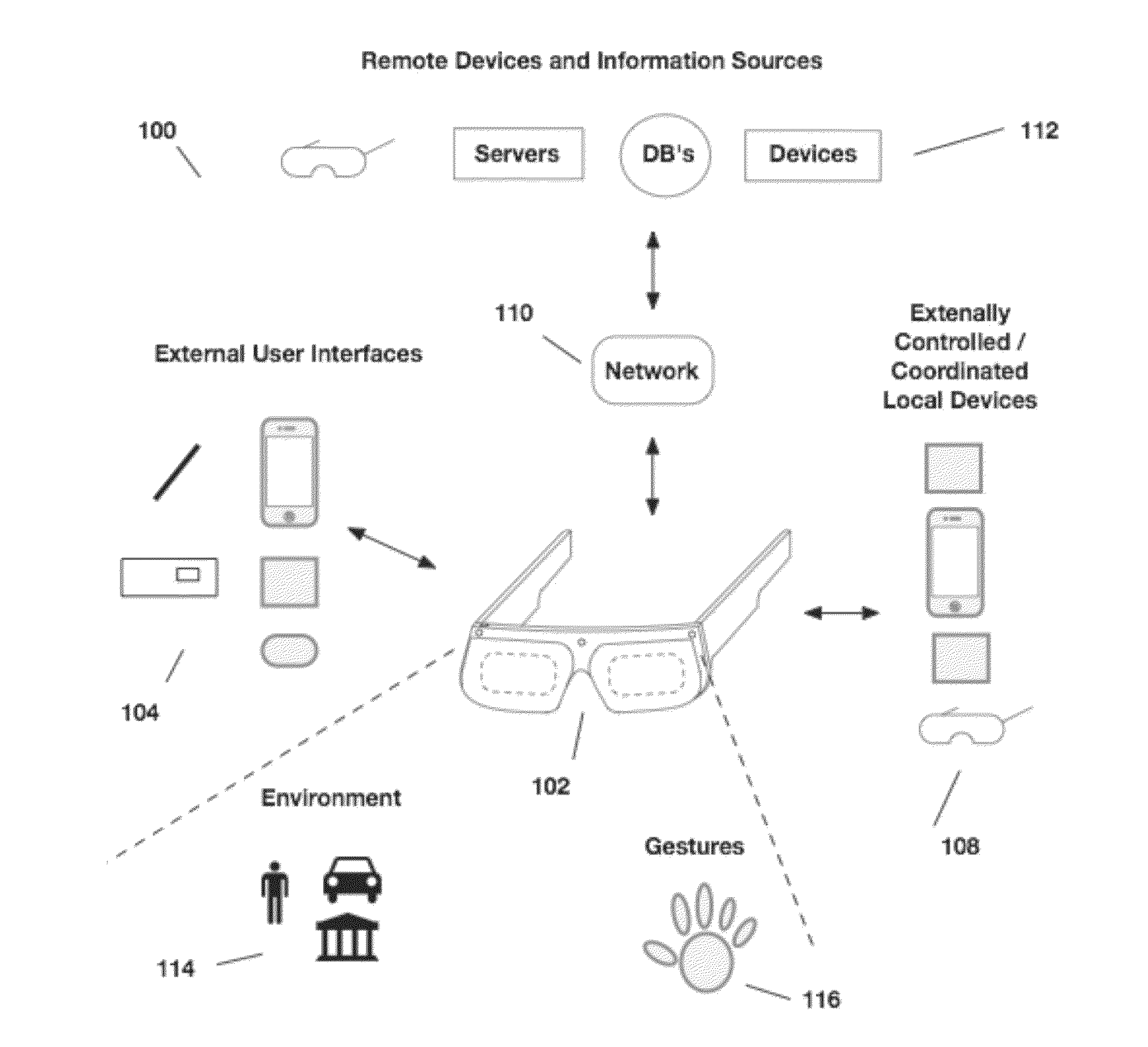
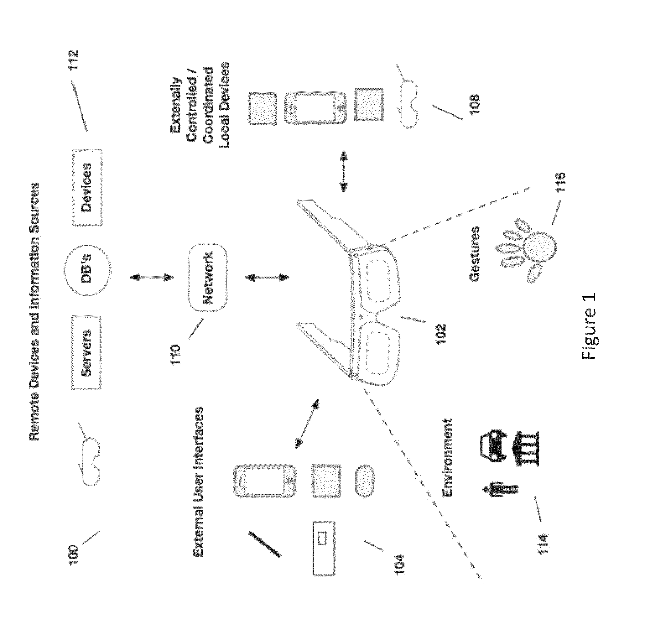
The present invention relates to reducing color breakup in content presented as sequentially colored sub-frames in a see-through head-worn display. The invention uses an eye imaging camera to track the user's eye position and make an accommodation based on detected eye movement. This allows for a faster frame rate and reduced color depth, which results in a system with reduced color breakup and a constant bandwidth. The invention also converts the displayed images to monochrome images with all the sequential colors applied simultaneously to eliminate color separation and color breakup. The bit depth of the displayed images is reduced to further reduce color breakup and the subframe rate is increased to address the issue.

Problems solved by technology

This stray light reduces the sharpness and contrast of the displayed image in the HMD.
In addition, the stray light causes the black areas of the displayed image to be gray and this effect adversely affects the see-through view of the environment because the see-through view is produced by the combination of the light from the environment and the light from the displayed image, which is in the best case the black portions of displayed image.

Method used


Image

  • See-through computer display systems
  • See-through computer display systems
  • See-through computer display systems

Examples


example 1

[0441]For a 26 deg display field of view and a 1280 pixel horizontally wide image, a pixel occupies 0.020 deg within the display field of view. If the frame rate of the full color images is 60 Hz, with three color sequential subframes images, the subframe time is 0.006 sec. The rotational speed of the head mounted display needed to produce one pixel of color breakup is then 3.6 deg / sec. If the number of horizontal pixels in the display field of view is reduced to 640 pixels and simultaneously the frame rate of the full color images is increased to 120 Hz, with three color sequential subframes images, the subframe time is reduced to 0.003, the size of a pixel is increased to 0.041 deg and the rotational speed to produce one pixel of color breakup is 14.6 deg / sec.

example 2

[0442]For a 26 deg display field of view and a 1280 pixel horizontally wide image, a pixel is 0.020 deg within the display field of view. If the smallest size that the user can detect for color breakup is one pixel wide, then a rotational speed of over 3.6 deg / sec is required if the subframe rate is 180 Hz, before color breakup is detected by the user. Even though the color breakup is an analog effect, the user's eye does not have the resolution to detect the color fringes that are present during movement below this speed. So below this rotational speed, color breakup management is not required.

example 3

[0443]For a 26 deg display field of view and a 1280 pixel horizontally wide image, a pixel is 0.020 deg within the display field of view. If the user can detect color breakup as small as one pixel wide, then a rotational speed of 3.6 deg / sec will require a shift of the subframes relative to each other of one pixel if the subframe rate is 180 Hz, to align the subframes so that color breakup is not visible to the user. If the user rotates their head at 15 deg / sec, then the subframes will require a shift of 4 pixels relative to one another to align the subframes so that color breakup is not visible. If the image frame begins with the display of the red subframe image, then no digital shifting is required for the red subframe image. A 4 pixel shift is required for the green subframe image. And, an 8 pixel shift is required for the blue subframe image. The next red subframe associated with the next image frame would then be effectively shifted 12 pixels relative to the previous red subfr...


PUM


Abstract

Aspects of the present invention relate to providing see-through computer display optics and reduction of color breakup in presented content.

Description

CROSS REFERENCE TO RELATED APPLICATIONS[0001]This application claims the benefit of priority to and is a continuation of U.S. application Ser. No. 14 / 554,039, filed Nov. 26, 2014 entitled SEE-THROUGH COMPUTER DISPLAY SYSTEMS.[0002]The above-identified application is incorporated herein by reference in its entirety.BACKGROUND[0003]1. Field of the Invention[0004]This invention relates to see-through computer display systems and reduction of color breakup in presented content.[0005]2. Description of Related Art[0006]Head mounted displays (HMD) and particularly HMDs that provide a see-through view of the environment are sensitive to the effects of stray light. Where, stray light includes light that is not intended to be included in the displayed image, including light that is scattered or inadvertently reflected from surfaces within the optics of the HMD. This stray light reduces the sharpness and contrast of the displayed image in the HMD. In addition, the stray light causes the black ...

Claims


Application Information

Patent Timeline
IPC IPC(8): G02B27/01G09G5/02
CPCG02B27/017G02B2027/0178G09G5/026G06F3/147G09G3/003G09G3/2003G09G5/028G09G2300/023G09G2310/0235G09G2320/0242G09G2320/0257G09G2320/0261G09G2320/0666G09G2340/0407G09G2340/0428G09G2340/0435G09G2340/0464G09G2350/00G09G2354/00G02B27/0172
Inventor BORDER, JOHN N.HADDICK, JOHN N.
Owner OSTERHOUT GROUP INC
Learn More