
Method of managing sensor network

a sensor network and sensor technology, applied in the field of managing sensor networks, can solve the problems of high maintenance cost of sensors networks, affecting the wider deployment of sensors in both developed countries, and the methodology used to operate the network of sensors may not maximize the information that could be provided by the network

Inactive Publication Date: 2016-05-19
FUJITSU LTD
View PDF6 Cites 100 Cited by
  • Summary
  • Abstract
  • Description
  • Claims
  • Application Information

AI Technical Summary

Benefits of technology

The patent describes a system where sensors and calibrators work together to estimate the values of certain parameters. The calibrator coordinates the process, using information from outside the sensor system and human input, to make the estimates more accurate. This way, the calibrator can detect and calibrate any sensors that may be missing this important step. The technical effect of this system is to improve the accuracy and reliability of sensor networks.

Problems solved by technology

However, the high maintenance cost of networks of sensors is an impediment to their wider deployment in both developed and less developed countries.
Individual sensors require maintenance including periodic calibration, repair or replacement in order to produce accurate measurements, but the cost of such maintenance may be prohibitive.
Once the sensors are deployed, the methodology used to operate the network of sensors may not maximize the information that could be provided by the network.
Replacing or manually recalibrating the sensors may be difficult and dangerous, for instance due to build-up of gases, and toxic or other dangerous materials making their way into the drainage system.
For these reasons, maintenance of such a sensor network is expensive.
Typically, sensors will have a limited lifetime due to environmental factors (heat or cold, exposure to sunlight, or battery depletion) and will therefore need replacing from time to time.
To date, however, such measures have not found widespread use.

Method used


Image

  • Method of managing sensor network
  • Method of managing sensor network
  • Method of managing sensor network

Examples


Embodiment Construction

[0081]Reference will now be made in detail to the embodiments, examples of which are illustrated in the accompanying drawings, wherein like reference numerals refer to the like elements throughout. The embodiments are described below to explain the present invention by referring to the figures.

[0082]With the aim of improving management of sensor networks, embodiments of the invention address three types of errors that may arise when using a large number of sensors placed in remote locations which are difficult and / or expensive to access for performing calibration, maintenance and replacement:

[0083](i) Loss of calibration of sensors

[0084](ii) Random errors inherent in sensor measurements, and

[0085](iii) Environment-dependent damage / degradation of the sensor.

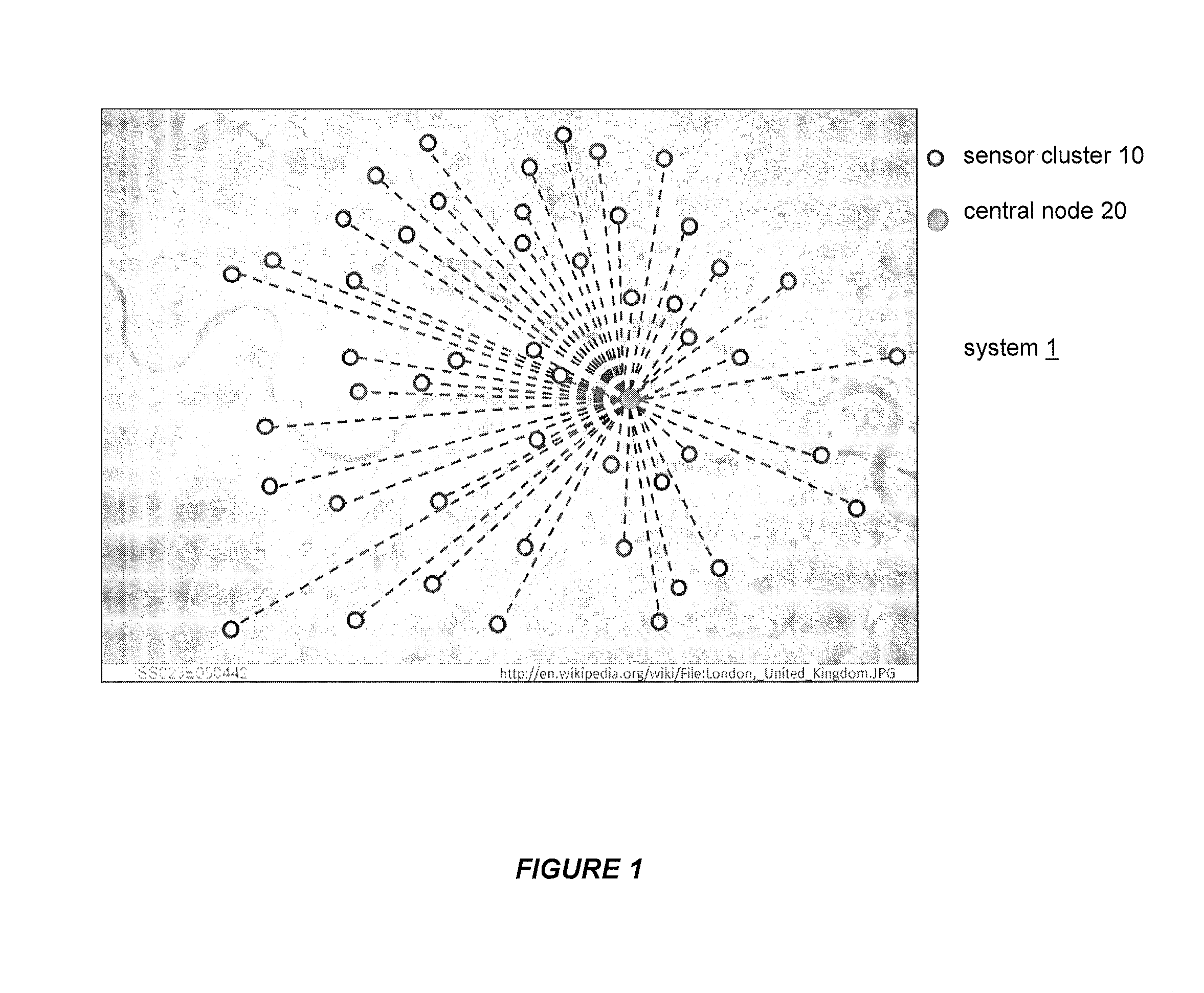
[0086]Embodiments provide a network (“sensor network”), made up of a plurality of groups of sensors preferably of different types (“sensor clusters”), where the sensor clusters need not be identical, that is to say each cluster ne...


PUM


Abstract

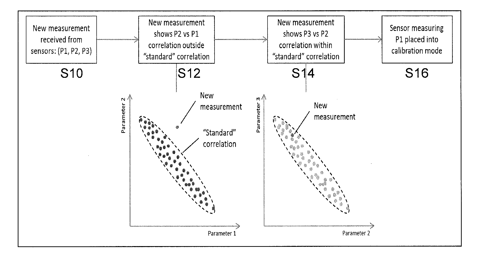
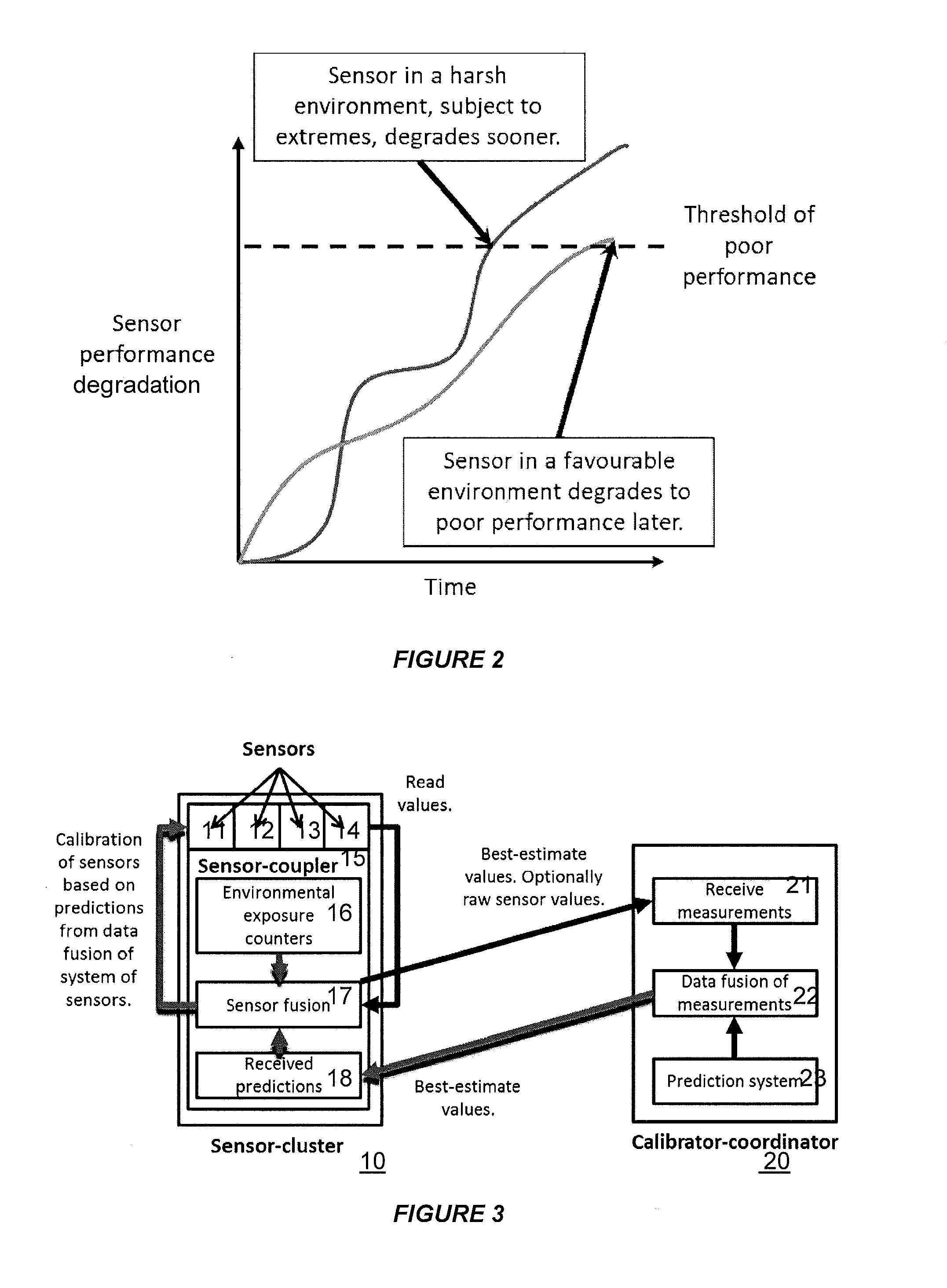
An environmental sensor system comprises a plurality of sensor clusters. The sensor coupler of each sensor cluster obtains measurements parameters from the sensors, performs processing on the measurements to obtain at least one result, and forwards information from the measurements to the calibrator coordinator. The calibrator coordinator performs processing on the information received from all of the sensor clusters to obtain at least one result, and feeds back the result to the sensor clusters which then assess sensor reliability and accuracy. The first and second results indicate expected parameter values, and each sensor coupler decides whether, and how, to incorporate the measurements of sensors into the first processing based on the expected values. The sensor coupler may calibrate, decommission or replace sensors determined to be unreliable based on the expected values.

Description

CROSS-REFERENCE TO RELATED APPLICATIONS[0001]This application claims the benefit of European Application No. 14191553.8, filed Nov. 3, 2014, in the European Intellectual Property Office, the disclosure of which is incorporated herein by reference.BACKGROUND[0002]1. Field[0003]The present invention relates to a method for maintaining and calibrating sensors in a sensor network, more particularly but not exclusively an environmental sensor network, as well as to a sensor network itself and apparatus for use in a sensor network.[0004]2. Description of the Related Art[0005]Networks of sensors have historically been important in many fields such as aeronautics, meteorology and climatology, and are becoming increasingly important for applications such as smart metering, autonomous cars and unmanned aerial vehicles.[0006]However, the high maintenance cost of networks of sensors is an impediment to their wider deployment in both developed and less developed countries. Individual sensors req...

Claims


Application Information

Patent Timeline
Patent Type & Authority Applications(United States)
IPC IPC(8): H04B17/11H04W4/00H04L69/40H04W4/38H04W4/70
CPCH04W4/005H04B17/11H04L67/12H04L69/40H04W84/18H04W4/70H04W4/38
Inventor WALKER, BRENTLI, MICHAEL
Owner FUJITSU LTD
Learn More