
Magnetic component

a technology of magnetic components and components, applied in the field of magnetic components, can solve the problems of huge eddy current loss, and achieve the effect of reducing the loss of magnetic components

Inactive Publication Date: 2016-05-19
DELTA ELECTRONICS INC
View PDF6 Cites 9 Cited by
  • Summary
  • Abstract
  • Description
  • Claims
  • Application Information

AI Technical Summary

Benefits of technology

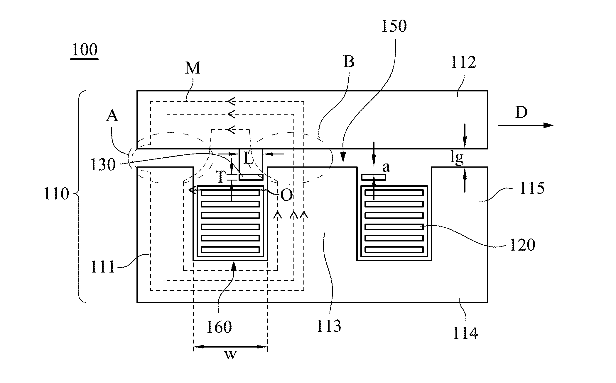
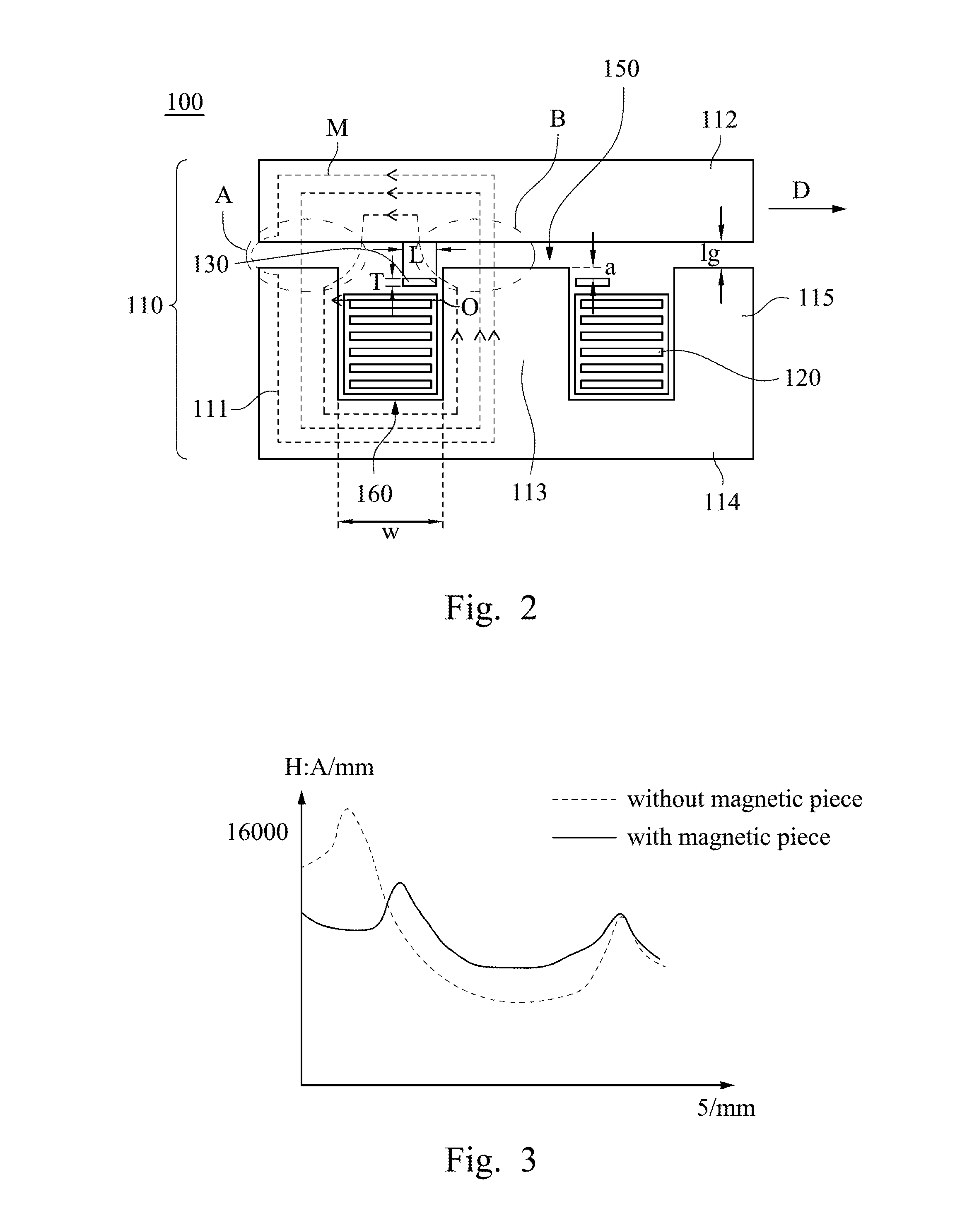
This patent describes a new type of magnetic component that can change the magnetic field distribution in a window and reduce the loss of the component. This is achieved by adding a magnetic piece between the air gap and the winding, which is parallel to the air gap direction and longer than it is wide. The magnetic piece has a relatively high initial permeability. This new design can improve the performance of the magnetic component and make it more efficient.

Problems solved by technology

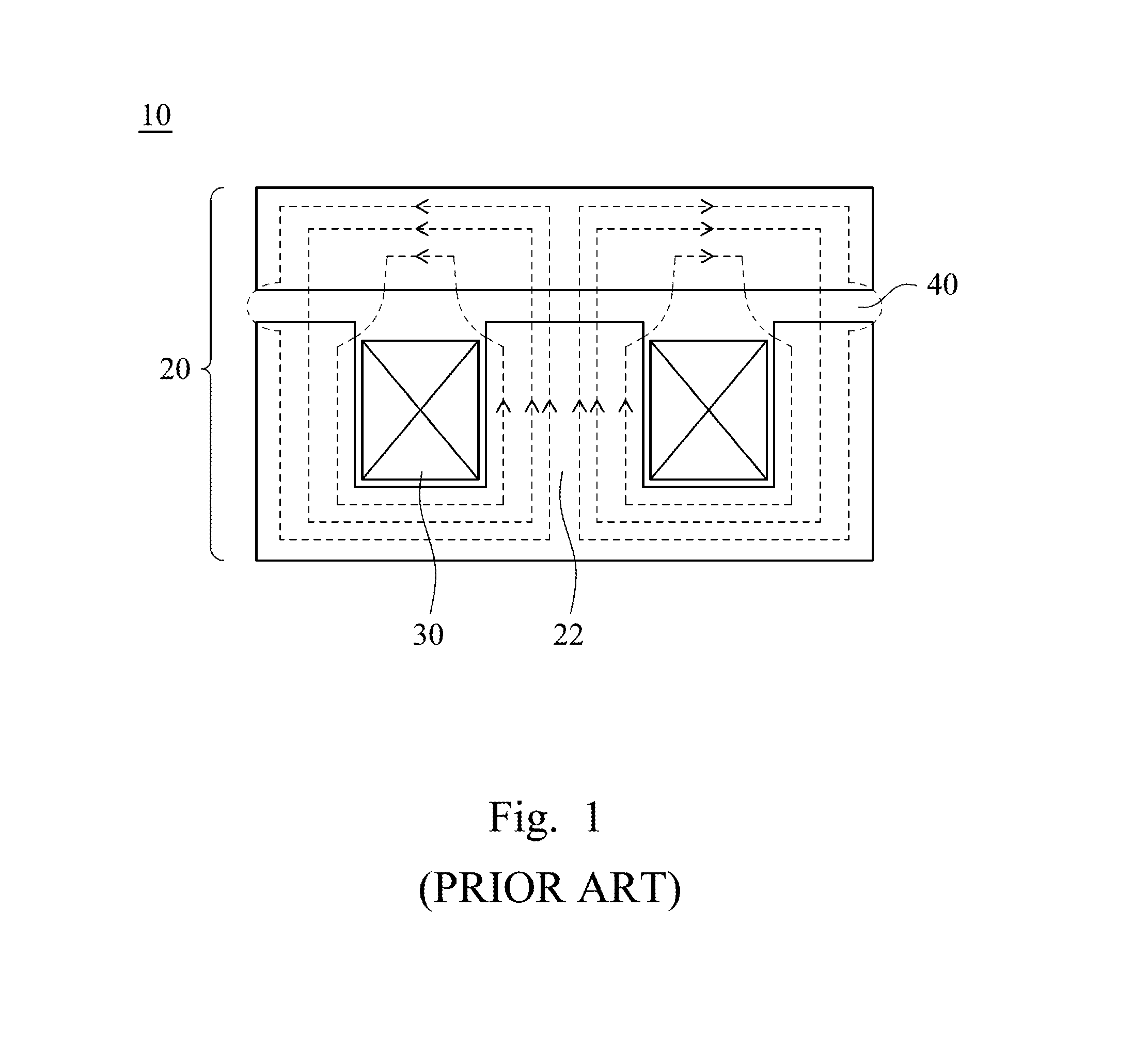
However, the magnetic field in the window of the ferrite magnetic core is not uniform, and the magnetic flux at the air gap may diffuse to the window thereby generating huge eddy current loss.
In the cases of magnetic components using the planar winding, the diffused magnetic flux is vertical to the longwise side of the planar winding, such situation may raise huge eddy current loss.

Method used


Image

  • Magnetic component
  • Magnetic component
  • Magnetic component

Examples


Embodiment Construction

[0018]Reference will now be made in detail to the present embodiments of the disclosure, examples of which are illustrated in the accompanying drawings. Wherever possible, the same reference numbers are used in the drawings and the description to refer to the same or like parts.

[0019]FIG. 1 is a cross-sectional view taken along a direction parallel to a magnetic flux of a conventional magnetic component. The magnetic component 10 includes an El type magnetic core 20, and a winding 30 wound on a middle column 22 of the magnetic core 20. The dotted line loop represents the magnetic flux of the magnetic component, and the arrow shows the direction of the magnetic flux, in which the magnetic flux direction is changed related to a current. The intensity of the magnetic field is stronger at the place close to the air gap 40 since the intensity of the magnetic field is weaker at the place close to the magnetic core 20. The magnetic flux is diffused into the window when the magnetic flux pa...


PUM

PropertyMeasurementUnit
widthaaaaaaaaaa
inductanceaaaaaaaaaa
thicknessaaaaaaaaaa

Abstract

A magnetic component includes a magnetic core, a winding, and a magnetic piece. The magnetic core includes at least one magnetic column, a top cover, and a bottom cover. The magnetic column is disposed between the top cover and the bottom cover, and an air gap is formed between the top cover and the magnetic column. The winding is wound on the magnetic column. The magnetic piece is disposed between the winding and the air gap, and the magnetic piece is arranged parallel to the air gap.

Description

RELATED APPLICATIONS[0001]This application claims priority to China Application Serial Number 201410657907.5, filed Nov. 17, 2014, which is herein incorporated by reference.BACKGROUND[0002]1. Field of Invention[0003]The present invention relates to a magnetic component.[0004]2. Description of Related Art[0005]With rapidly developments of wind powers, solar powers, vehicle electronics, power module having high-frequency and high power density, or the likes, the requirements, such as volume, efficiency, and power density, for the magnetic components, such as inductors and transformers, in the power electronic device are higher and higher. The magnetic component has a magnetic core, and the magnetic core can be made of magnetic powder material with lower permeability, such as a Fe—Si magnetic powder core, a Fe-Sl-Ni magnetic powder core, or the likes. The magnetic core can be made of a magnetic material with higher permeability, such as ferrite, amorphous, silicon steel or the likes. W...

Claims


Application Information

Patent Timeline
Patent Type & Authority Applications(United States)
IPC IPC(8): H01F27/24H01F27/32H01F27/28
CPCH01F27/24H01F27/323H01F27/325H01F27/2823H01F3/14H01F27/346H01F2027/348
Inventor DAI, MING-HUIZHOU, JIN-PINGZHOU, MIN
Owner DELTA ELECTRONICS INC
Learn More