
Electric propulsion assembly for an aircraft

a technology for electric propulsion and aircraft, which is applied in the field of electric propulsion assembly for aircraft, can solve the problems of inability to apply aeronautics solutions, increase the amount of heat dissipation of power electronics systems, and the overall weight of the propulsion unit, so as to reduce the weight associated with wiring, increase the efficiency of the exchanger, and reduce the effect of mass

Active Publication Date: 2016-05-19
AIRBUS SAS
View PDF4 Cites 30 Cited by
  • Summary
  • Abstract
  • Description
  • Claims
  • Application Information

AI Technical Summary

Benefits of technology

The patent text describes a system where a power electronics system is placed in the same area as the fan in an aircraft. This allows for better use of the air generated by the fan, which can increase the efficiency of the system. The placement also reduces the weight associated with wiring the propulsion assembly. Overall, this setup can make the system more efficient and lighter.

Problems solved by technology

The need to procure higher propulsion powers for larger airplanes results in a significant increase in the amount of heat dissipated by the power electronics systems used to manage and control the amount of electrical energy delivered to the electric drive.
However, all of these solutions of the prior art are penalizing in terms of the additional weight (fluid, circulatory system, etc.) that they add to the power electronics systems.
However, such a solution cannot be applied to the field of aeronautics because of the significant additional weight that recourse to such a solution for removing the heat dissipated by a power electronics system of a propulsion unit of a large sized aircraft would have.
In addition, the weight of the various wiring used to supply electrical power or to transmit the electrical control signals, for example, is a significant factor in the overall weight of the propulsion unit, this weight penalizing the payload of the airplane.

Method used


Image

  • Electric propulsion assembly for an aircraft
  • Electric propulsion assembly for an aircraft

Examples


Embodiment Construction

[0038]It will be noted first of all that the figures are not to scale.

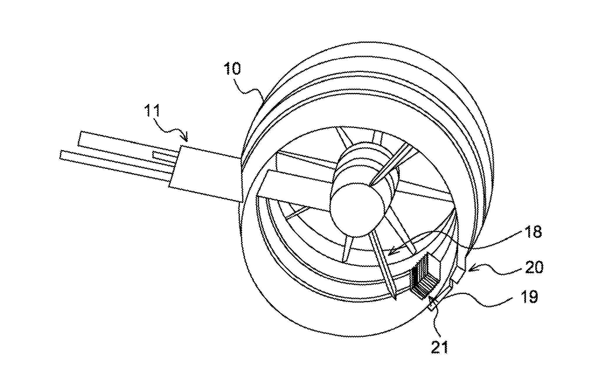
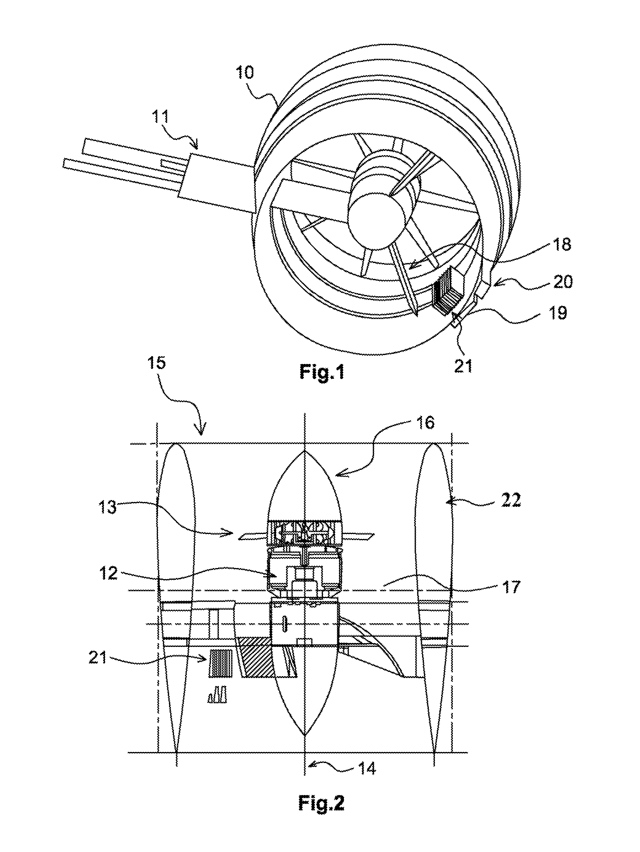
[0039]FIGS. 1 and 2 show a hybrid electric propulsion assembly for an airplane according to a preferred embodiment of the invention.

[0040]This propulsion assembly comprises a nacelle 10 intended to be assembled by means of a mechanical connection 11 such as a pylon to a structural element of an aircraft. Purely by way of illustration, this structural element could be part of the wing structure of the aircraft, the assembly for example being positioned at the tip of this wing structure. This assembly could, however, be attached to some other point of the wing structure of this aircraft.

[0041]The nacelle 10 comprises a nacelle cowl 10 delimiting an internal volume in which an electric motor 12 that drives a fan 13 installed in front of this electric motor 12 is positioned. The nacelle 10 is arranged coaxially around the electric motor 12 about a longitudinal axis 14.

[0042]Simplistically, this propulsion assembly dra...


PUM


Abstract

An electric propulsion assembly for an aircraft includes a nacelle having a nacelle cowl which defines an inner space for arranging an electric propulsion unit, which includes a blower, of the aircraft. An electric motor assembly is placed in the inner space and connected to the propulsion unit to supply power to the propulsion unit. An airflow generated by the blower flows in a space between the motor assembly and the nacelle cowl defining a duct to supply thrust to the aircraft. A power electronics system has at least one heat exchanger to transfer thermal energy from the system to a work fluid to cool the system. The heat exchanger is placed to project at least partially into the duct, so that the work fluid consists of the air flow generated by the blower.

Description

BACKGROUND OF THE INVENTION[0001]1. Field of the Invention[0002]The present invention relates to an electric propulsion assembly for an aircraft having a novel design for cooling the power electronics system thereof.[0003]The invention also relates to an aircraft provided with such an electric propulsion assembly.[0004]2. Technical Background[0005]The aeronautical industry is a technical field that is constantly evolving and always seeking technological advancements. It is within this context that current research work seeking to reduce the environmental impact of air transport, notably noise and the emission of greenhouse gases falls.[0006]In this context, the concepts of mechanical / electrical hybrid drive or all-electric drive are very promising. Thus, small airplanes such as two-seat private airplanes, all of the propulsion of which is provided by electrical power, are known.[0007]The need to procure higher propulsion powers for larger airplanes results in a significant increase ...

Claims


Application Information

Patent Timeline
IPC IPC(8): B64D27/24B64D33/10B64D29/02
CPCB64D27/24B64D33/10B64D29/02B64D33/08B64D2033/024Y02T50/40Y02T50/60F04D25/082F04D25/08F04D25/0693F04D29/584F04D29/5813F04D25/12F04D29/5806F04D25/068
Inventor JOUBERT, EMMANUELSMAOUI, HICHEMNESPOULOUS, CHARLESRECHAIN, BRUNO
Owner AIRBUS SAS
Learn More