
Hybrid-power driving system for a vehicle and a transmission thereof

a hybrid power driving and transmission technology, applied in mechanical equipment, transportation and packaging, gearing, etc., can solve the problems of limiting the power of the em and the power capacity of the vehicle, limiting the size, and unable to improve the fuel use efficiency in significant respect to non-hybrid vehicles

Active Publication Date: 2016-05-19
SAIC MOTOR
View PDF4 Cites 14 Cited by
  • Summary
  • Abstract
  • Description
  • Claims
  • Application Information

AI Technical Summary

Benefits of technology

This patent describes a new technology that allows for better control and optimization of a computer network. The technology can adjust various parameters, such as network bandwidth and timing, to improve the overall performance and reliability of the network. The invention has been designed to be flexible and adaptable, so it can be used in different types of networks and achieve different objectives. Overall, the patent presents a valuable tool for enhancing the efficiency and effectiveness of computer networks.

Problems solved by technology

Deploying those hybrid-power vehicle components in such a layout can result in limiting the size of the EM, and as a result, limiting the power of the EM and the power capacity of the vehicle.
As such, the fuel use efficiency cannot be improved significantly with respect to non-hybrid vehicles.
Furthermore, the driving ability in a pure motor driving mode is not satisfying when the power of the EM is too low.
Furthermore still, in current vehicle hybrid-power driving systems, driving comfort cannot be ensured since power interruption cannot be avoided automatically in the configuration having a single clutch.
In a known vehicle hybrid-power driving system, the power transmitting path of the EM is joined midway into several of the power transmitting paths of the ICE, which results in a vehicle hybrid-power driving system having complex power transmitting paths.

Method used


Image

  • Hybrid-power driving system for a vehicle and a transmission thereof
  • Hybrid-power driving system for a vehicle and a transmission thereof
  • Hybrid-power driving system for a vehicle and a transmission thereof

Examples


example 1

A Hybrid-Power Driving System (HPDS) (100, 200) Comprising

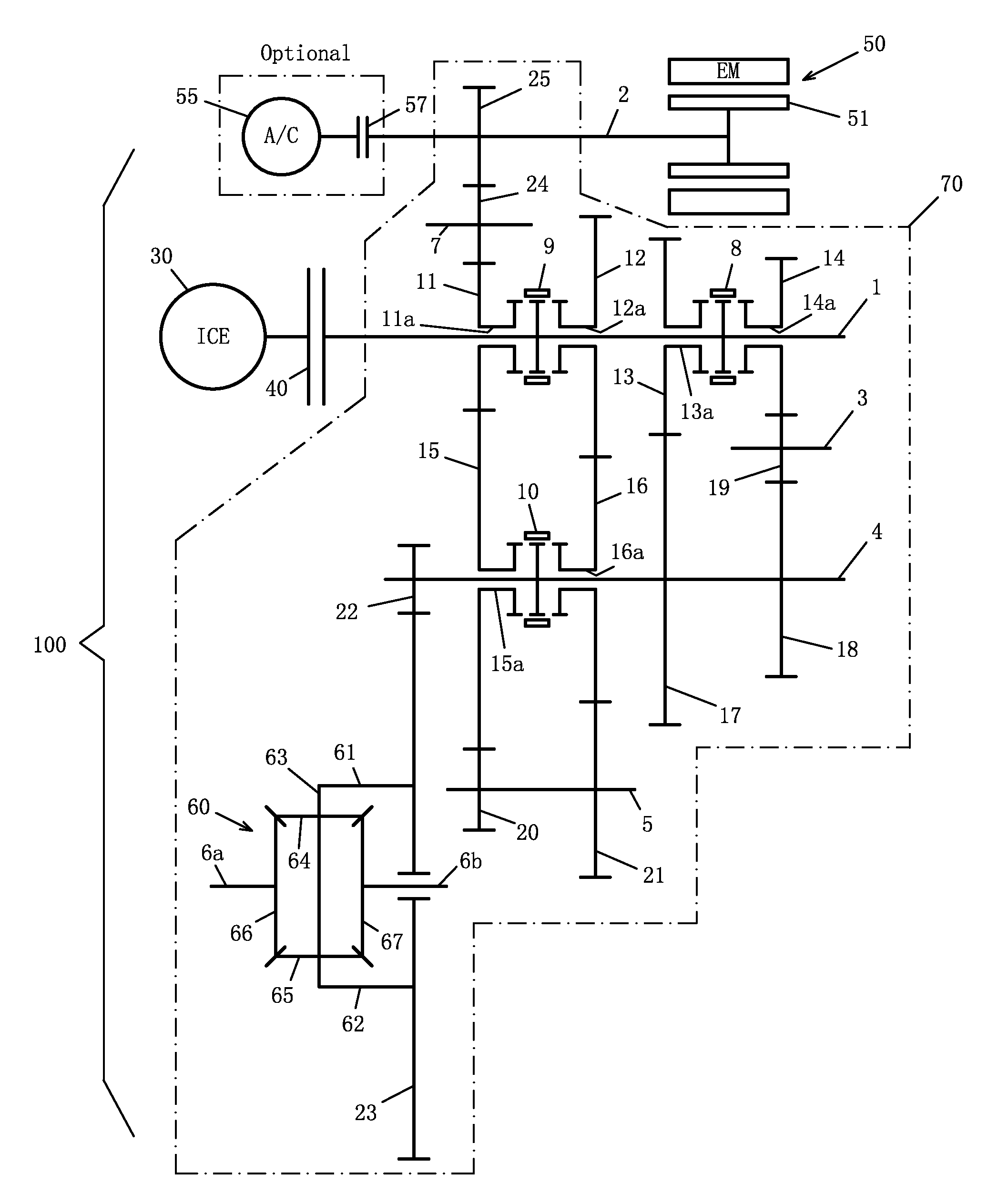
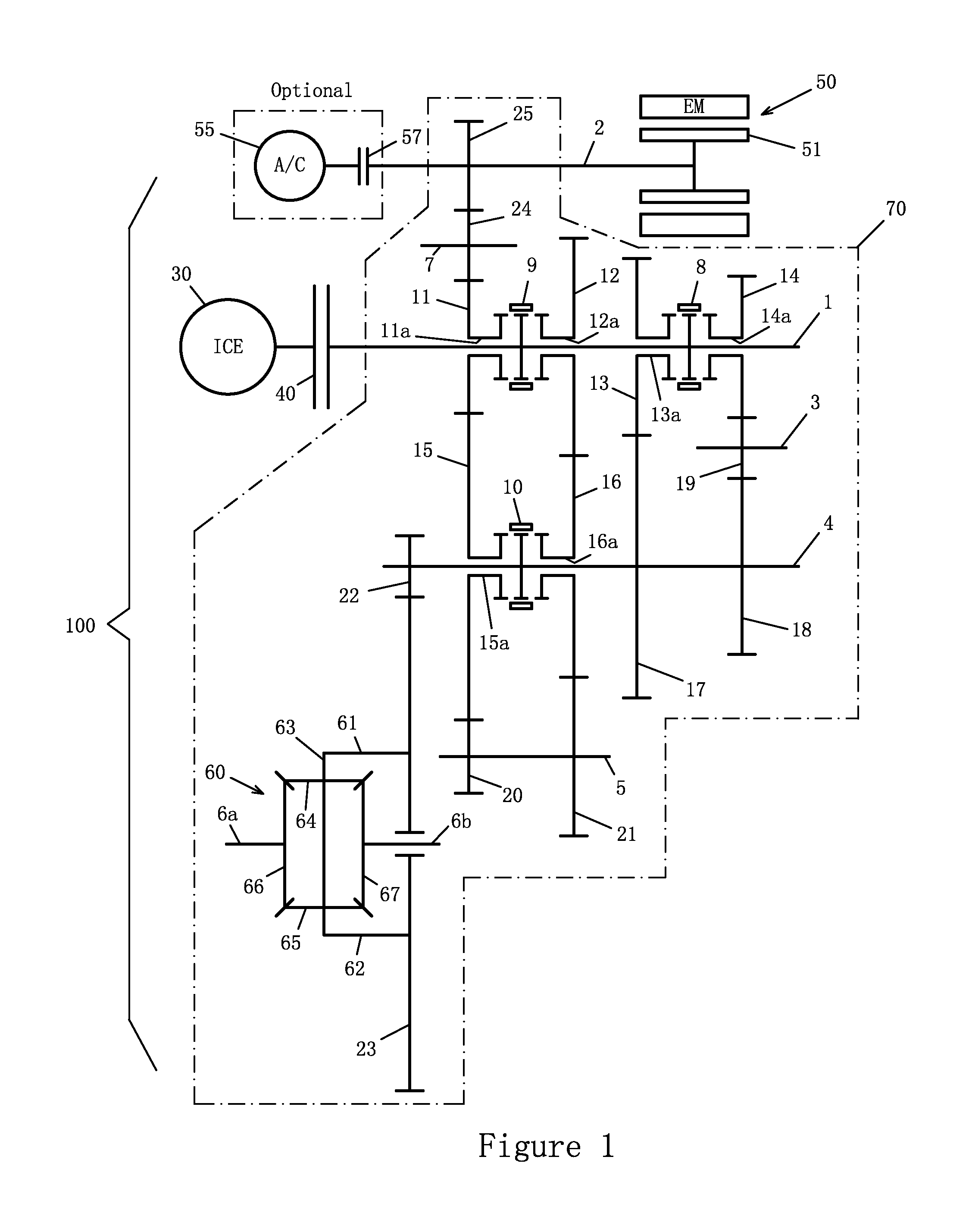
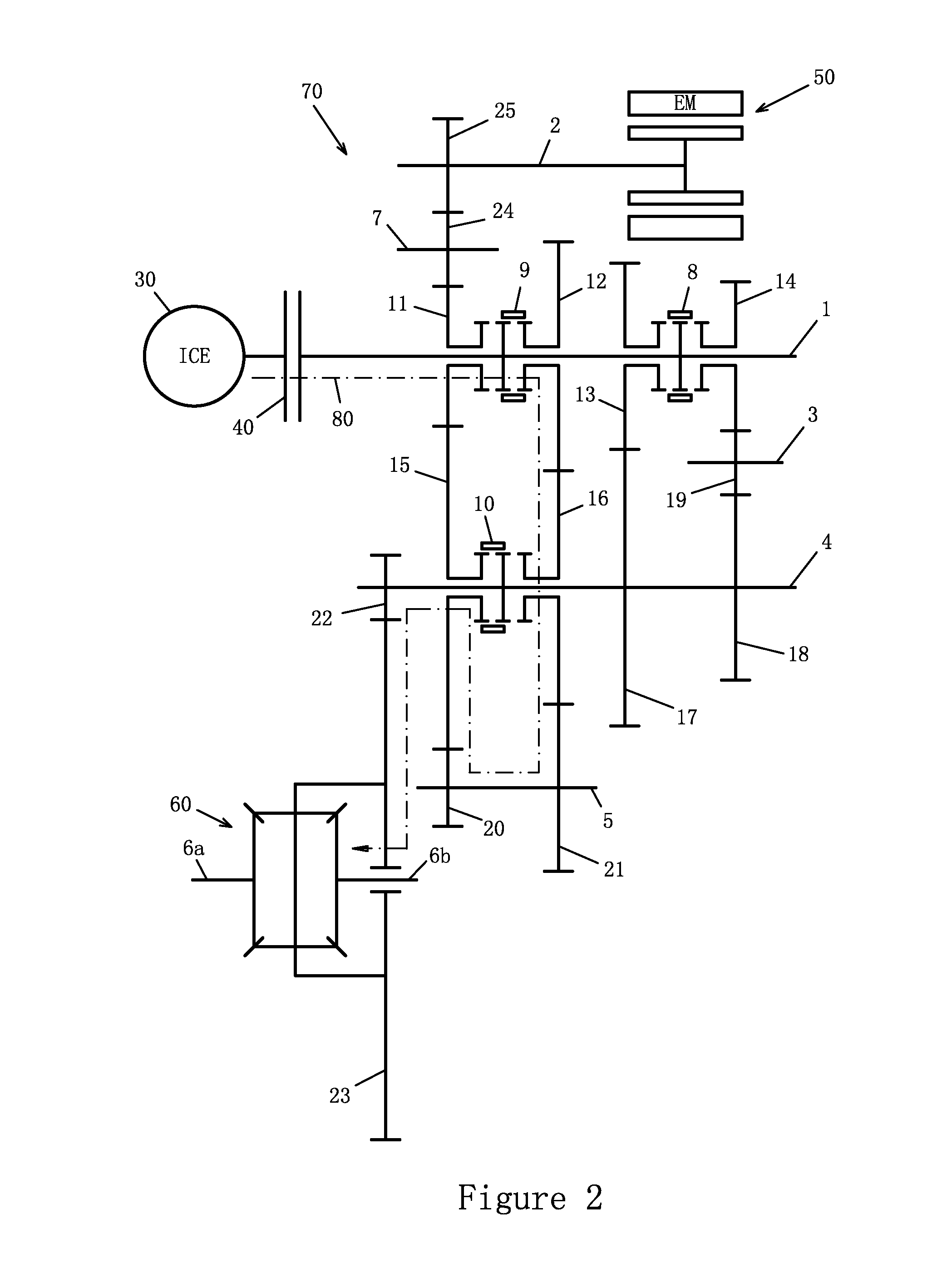
[0182]an input shaft (1, 101) having disposed thereon a first driving gearwheel (11, 111), a second driving gearwheel (12, 112), a third driving gearwheel (13, 113), a reverse-gear driving gearwheel (14, 114), a first synchronizer (9, 109), and a second synchronizer (8, 108), wherein the first synchronizer (9, 109) is disposed between the first driving gearwheel (11, 111) and the second driving gearwheel (12, 112), and wherein the second synchronizer (8, 108) is disposed between the third driving gearwheel (13, 113) and the reverse-gear driving gearwheel (14, 114);

[0183]a first intermediate shaft (4, 104) having disposed thereon a first speed-reducing gearwheel (22, 122), a first driven gearwheel (15, 115), a second driven gearwheel (16, 116), a third driven gearwheel (17, 117), a reverse-gear driven gearwheel (18, 118), and a third synchronizer (10, 110), wherein the third synchronizer (10, 110) is disposed between the first...

example 2

[0189]The hybrid-power driving system of EXAMPLE 1, further comprising: a pair of half-axles (6a and 6b, 106a and 106b) connected to the differential (60, 160).

example 3

[0190]The hybrid-power driving system of EXAMPLE 2, wherein the input shaft (1, 101), the motor shaft (2, 102) the first idler shaft (3, 103) the first intermediate shaft (4, 104), the second intermediate shaft (5, 105), and the pair of half-axles (6a and 6b, 106a and 106b) are parallel to each other.


PUM


Abstract

A hybrid-power driving system (HPDS) (100, 200) includes an engine, a motor, and a transmission. The HPDS may include a single clutch and the transmission can provide at least five forward speed ratios and can provide for at least one reverse speed ratio. The transmission can include three synchronizers and multiple gearwheels that are used in multiple speed ratios. In addition to a pure engine driving mode and a pure motor driving mode, the HPDS can operate using a hybrid-power driving mode (HDM). In the HDM, the HPDS can provide for shifting of gears without power interruption to the output shaft or half-axles and wheels of a vehicle. In the HDM, the continuous power being output can be achieved by keeping a synchronizer engaged with a gearwheel for two consecutive speed ratios.

Description

CROSS REFERENCE TO RELATED APPLICATIONS[0001]This application claims the benefit of priority to Chinese Patent Application No. 201410658447.8, filed Nov. 18, 2014, the contents of which are incorporated entirely herein by reference BACKGROUND[0002]Unless otherwise indicated herein, the elements described in this section, the technical field, and the background art are not prior art to the claims and are not admitted to be prior art by inclusion in this section.[0003]A. Technical Field[0004]This application relates to a vehicle hybrid-power driving system. A vehicle hybrid-power driving system described in this application can include synchronizers that are cooperatively switched and gearwheels that are shared in different gear ratios (i.e., speed ratios), so that a compact structure of the system can be obtained and effective cooperation of an electric motor (or more simply, “EM”) and an internal combustion engine (or more simply, “engine” or “ICE”) in multiple speed ratios can be a...

Claims


Application Information

Patent Timeline
Patent Type & Authority Applications(United States)
IPC IPC(8): B60K6/365B60K6/48B60K6/547F16H37/08
CPCB60K6/365F16H37/0806B60K6/48B60K6/547F16H2037/049F16H2200/0021F16H2200/0086F16H2702/04Y10S903/91Y10S903/919B60Y2200/92F16H2200/0047F16H3/091B60K2006/4816B60K2006/4841F16H2003/0826F16H2200/0052Y02T10/62
Inventor ZHU, JUNWANG, JIANGE, HAILONGFU, ZHENXINGLUO, SIDONGLIU, MIN
Owner SAIC MOTOR
Learn More