
Method and system for image processing to determine patient-specific blood flow characteristics

a technology of image processing and patient-specific blood flow, applied in the field of method and system for patient-specific modeling of fluid flow, can solve the problems of limiting blood flow to the heart, myocardial infarction, heart attack, etc., and unable to provide direct assessment of coronary lesions or assess blood flow ra

Active Publication Date: 2016-05-12
HEARTFLOW
View PDF0 Cites 42 Cited by
  • Summary
  • Abstract
  • Description
  • Claims
  • Application Information

AI Technical Summary

Benefits of technology

The patent describes new features and benefits that can be achieved by using certain parts and configurations. These features and benefits are intended to improve the performance of the invention and make it more effective in solving relevant problems.

Problems solved by technology

As a result, blood flow to the heart may be restricted.
A more severe manifestation of disease may lead to myocardial infarction, or heart attack.
These noninvasive tests, however, typically do not provide a direct assessment of coronary lesions or assess blood flow rates.
However, CCTA also cannot provide direct information on the functional significance of coronary lesions, e.g., whether the lesions affect blood flow.
In addition, since CCTA is purely a diagnostic test, it cannot be used to predict changes in coronary blood flow, pressure, or myocardial perfusion under other physiologic states, e.g., exercise, nor can it be used to predict outcomes of interventions.
CCA, however, does not provide data for assessing the functional significance of coronary lesions.
For example, a doctor may not be able to diagnose whether a coronary lesion is harmful without determining whether the lesion is functionally significant.
As a result, CCA may lead to unnecessary operations on the patient, which may pose added risks to patients and may result in unnecessary heath care costs for patients.
Thus, the decision to treat a lesion based on the determined FFR may be made after the initial cost and risk of diagnostic cardiac catheterization has already been incurred.

Method used


Image

  • Method and system for image processing to determine patient-specific blood flow characteristics
  • Method and system for image processing to determine patient-specific blood flow characteristics
  • Method and system for image processing to determine patient-specific blood flow characteristics

Examples


Embodiment Construction

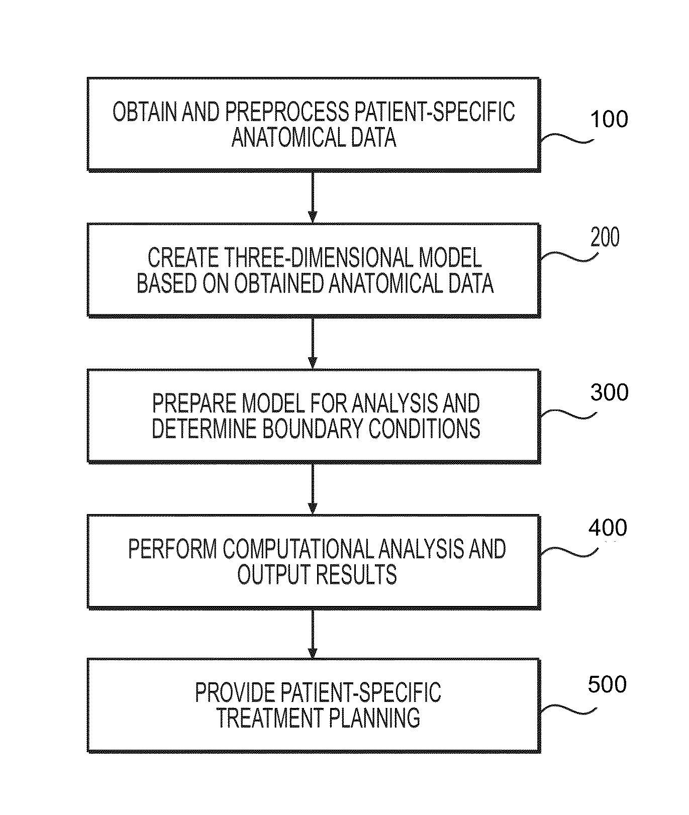
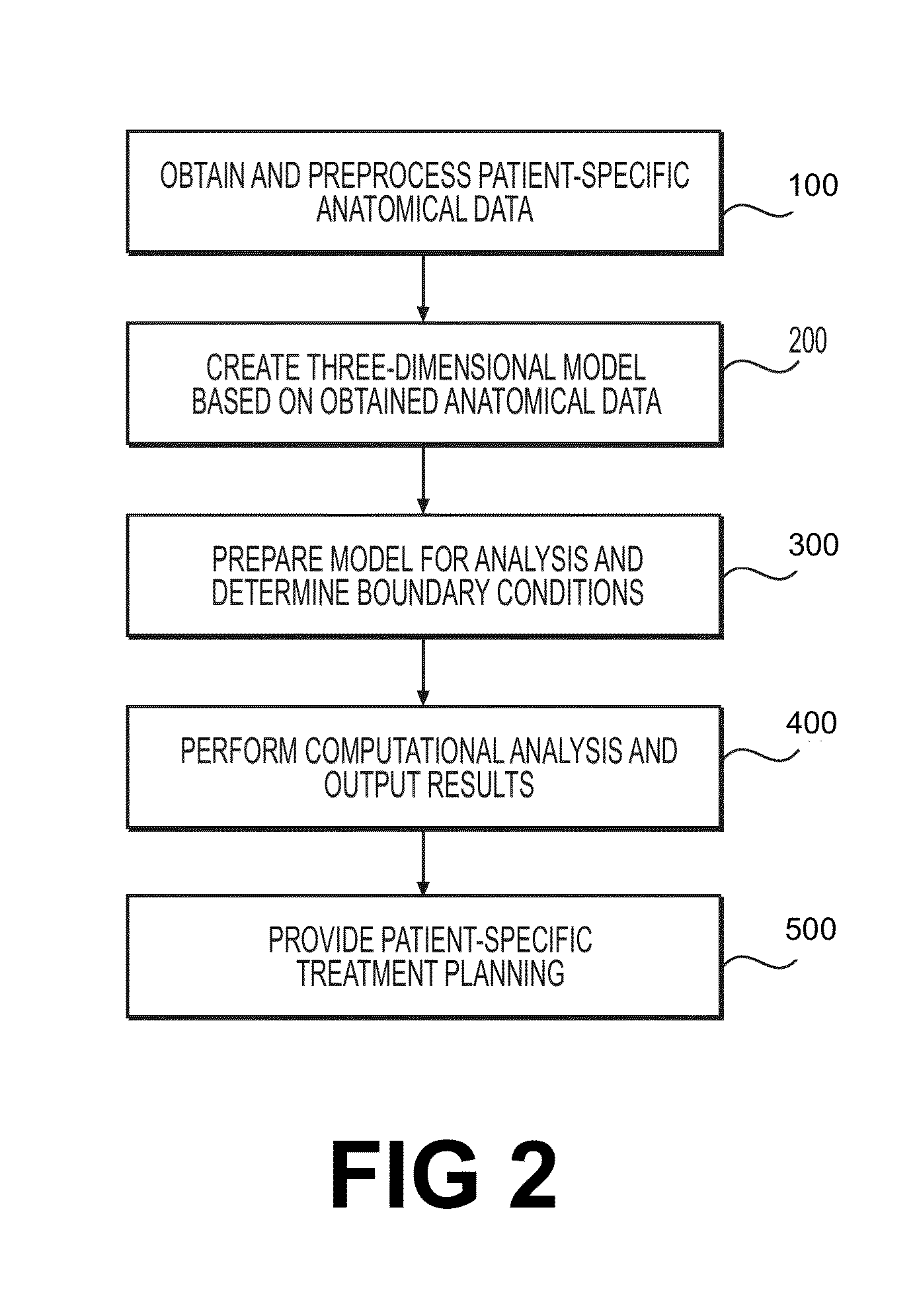
[0080]Reference will now be made in detail to exemplary embodiments, examples of which are illustrated in the accompanying drawings. Wherever possible, the same reference numbers will be used throughout the drawings to refer to the same or like parts. This description is organized according to the following outline:[0081]I. Overview[0082]II. Obtaining and Preprocessing Patient-Specific Anatomical Data[0083]III. Creating The Three-Dimensional Model Based On Obtained Anatomical Data[0084]IV. Preparing The Model For Analysis and Determining Boundary Conditions[0085]A. Preparing the Model For Analysis[0086]B. Determining Boundary Conditions[0087]i. Determining Reduced Order Models[0088]ii. Exemplary Lumped Parameter Models[0089]C. Creating the Three-Dimensional Mesh[0090]V. Performing The Computational Analysis And Outputting Results[0091]A. Performing the Computational Analysis[0092]B. Displaying Results for Blood Pressure, Flow, and cFFR[0093]C. Verifying Results[0094]D. Another Embod...


PUM


Abstract

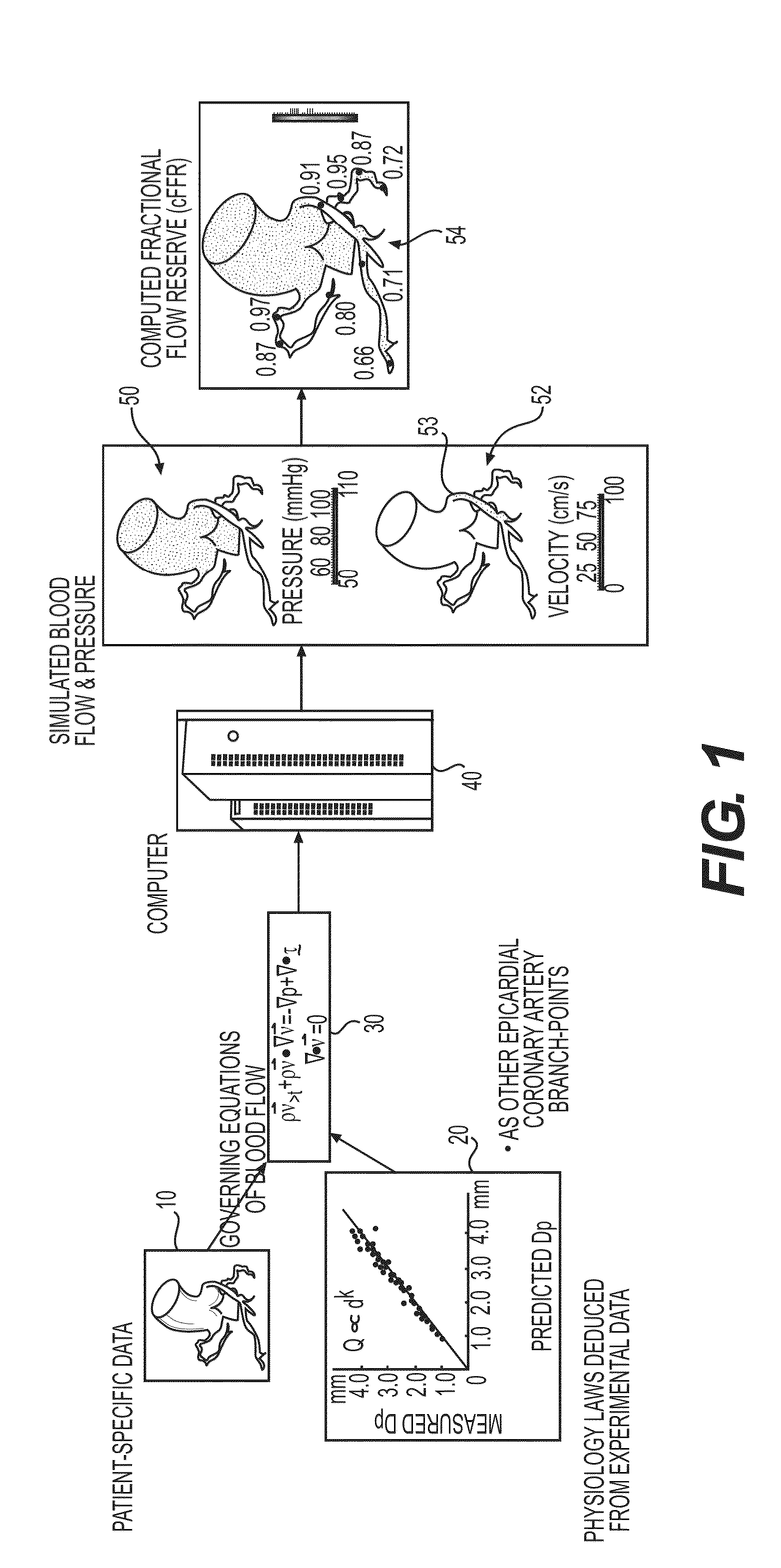
Embodiments include a system for determining cardiovascular information for a patient. The system may include at least one computer system configured to receive patient-specific data regarding a geometry of the patient's heart, and create a three-dimensional model representing at least a portion of the patient's heart based on the patient-specific data. The at least one computer system may be further configured to create a physics-based model relating to a blood flow characteristic of the patient's heart and determine a fractional flow reserve within the patient's heart based on the three-dimensional model and the physics-based model.

Description

PRIORITY[0001]This application claims the benefit of priority from U.S. Provisional Application No. 61 / 401,462, filed Aug. 12, 2010, U.S. Provisional Application No. 61 / 401,915, filed Aug. 20, 2010, U.S. Provisional Application No. 61 / 402,308, filed Aug. 26, 2010, U.S. Provisional Application No. 61 / 402,345, filed Aug. 27, 2010, and U.S. Provisional Application No. 61 / 404,429, filed Oct. 1, 2010, which are herein incorporated by reference in their entirety.TECHNICAL FIELD[0002]Embodiments include methods and systems for modeling of fluid flow and more particularly methods and systems for patient-specific modeling of blood flow.BACKGROUND[0003]Coronary artery disease may produce coronary lesions in the blood vessels providing blood to the heart, such as a stenosis (abnormal narrowing of a blood vessel). As a result, blood flow to the heart may be restricted. A patient suffering from coronary artery disease may experience chest pain, referred to as chronic stable angina during physica...

Claims


Application Information

Patent Timeline
Patent Type & Authority Applications(United States)
IPC IPC(8): G06T7/00G06T17/00G06T7/20G06T7/60A61B6/00G06K9/46G16B45/00
CPCG06T7/0012A61B6/504A61B6/507A61B6/5205A61B6/5217G06T2207/30104G06K9/46G06T7/20G06T7/602G06T17/005G06T2207/30048G06T7/0081G16H50/50A61B5/0035A61B5/004A61B5/0044A61B5/02A61B5/02007A61B5/02028A61B5/021A61B5/024A61B5/026A61B5/0263A61B5/029A61B5/055A61B5/1075A61B5/1118A61B5/4848A61B5/6852A61B5/7246A61B5/7275A61B5/7278A61B5/745A61B6/032A61B6/503A61B6/5229A61B8/04A61B8/06A61B8/065A61B8/481A61B8/5223A61B8/5261A61B2576/023A61B2576/00A61B2034/104A61B2090/374A61B2090/3762G06T7/70G06T7/73G06T7/74G06T7/11G06T7/12G06T7/13G06T7/149G06T7/62G16H10/60G16H50/30A61B34/10A61B2034/105A61B34/25G16H30/20G16H70/00Y02A90/10G16B45/00G16H50/20G16H30/40G06V20/653G06V10/764G06F17/10G16B5/00G06F30/20G06F30/23G06T7/10A61B5/6868G06T2207/30016G06V20/698G06F18/22G06F18/24G06V10/467G06V10/42G06V10/40G06V10/44G06F30/28G06G7/60G01R33/56366G06T17/00A61B5/22G06T11/001G06T11/20A61M5/007G06T2200/04G06T2207/10081A61B6/03G06T2210/41G06T17/20G06T2207/10088G06T11/00G06T2207/10072G06T2207/20036G06T15/10G06T7/0014G06T11/60A61B6/481A61B2090/3764A61B2034/108G06T11/008G06T2207/20124G06T2211/404G06T7/60A61B2034/107A61B8/02G06T2207/10104G06T2207/10108G01R33/5601G01R33/5635G06T2207/10012G16H10/40G16H50/70
Inventor TAYLOR, CHARLES A.
Owner HEARTFLOW
Learn More