Electric linear motion actuator and electric brake system

a technology of electric brake system and actuator, which is applied in mechanical equipment, transportation and packaging, and machining, etc., can solve the problems of large power consumption of electric motor, and achieve the effect of reducing costs and facilitating assembly of electric linear motion actuators

Active Publication Date: 2016-05-12
NTN CORP
View PDF7 Cites 12 Cited by
  • Summary
  • Abstract
  • Description
  • Claims
  • Application Information

AI Technical Summary

Benefits of technology

The present invention provides an electric linear motion actuator with a built-in electric locking mechanism that keeps the power transmission path in the locked state when energized. This results in a more convenient and easy attachment of the electric motor and the electric locking mechanism to the actuator. Additionally, since the electric locking mechanism is received in the motor case, there is no need for separate waterproof treatment, reducing costs.

Problems solved by technology

As a result thereof, since while the vehicle is parked, a braking force needs to be maintained by keeping the electric motor energized, there is the disadvantage that the power consumption of the electric motor is large.

Method used


Image

  • Electric linear motion actuator and electric brake system
  • Electric linear motion actuator and electric brake system
  • Electric linear motion actuator and electric brake system

Examples


Embodiment Construction

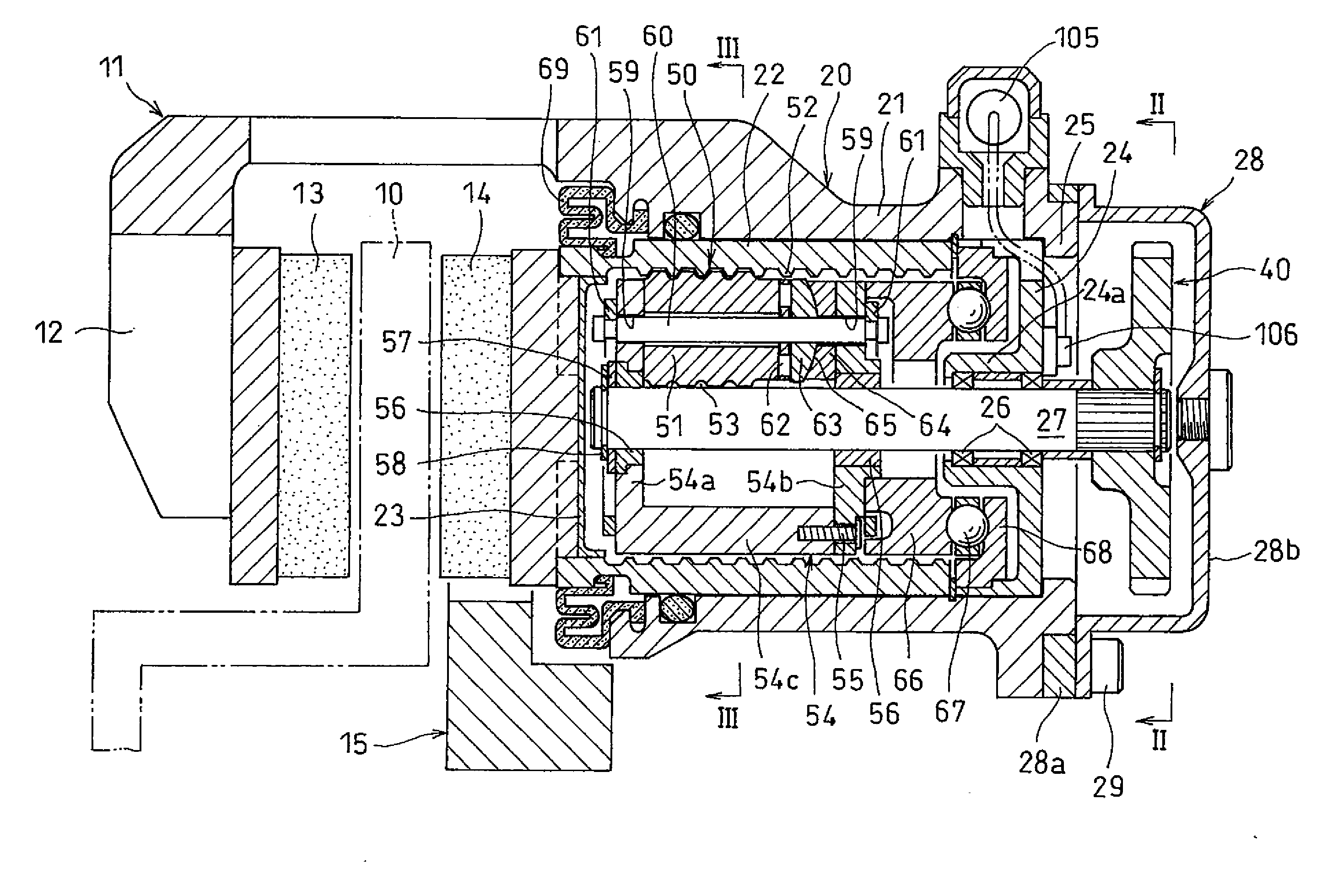
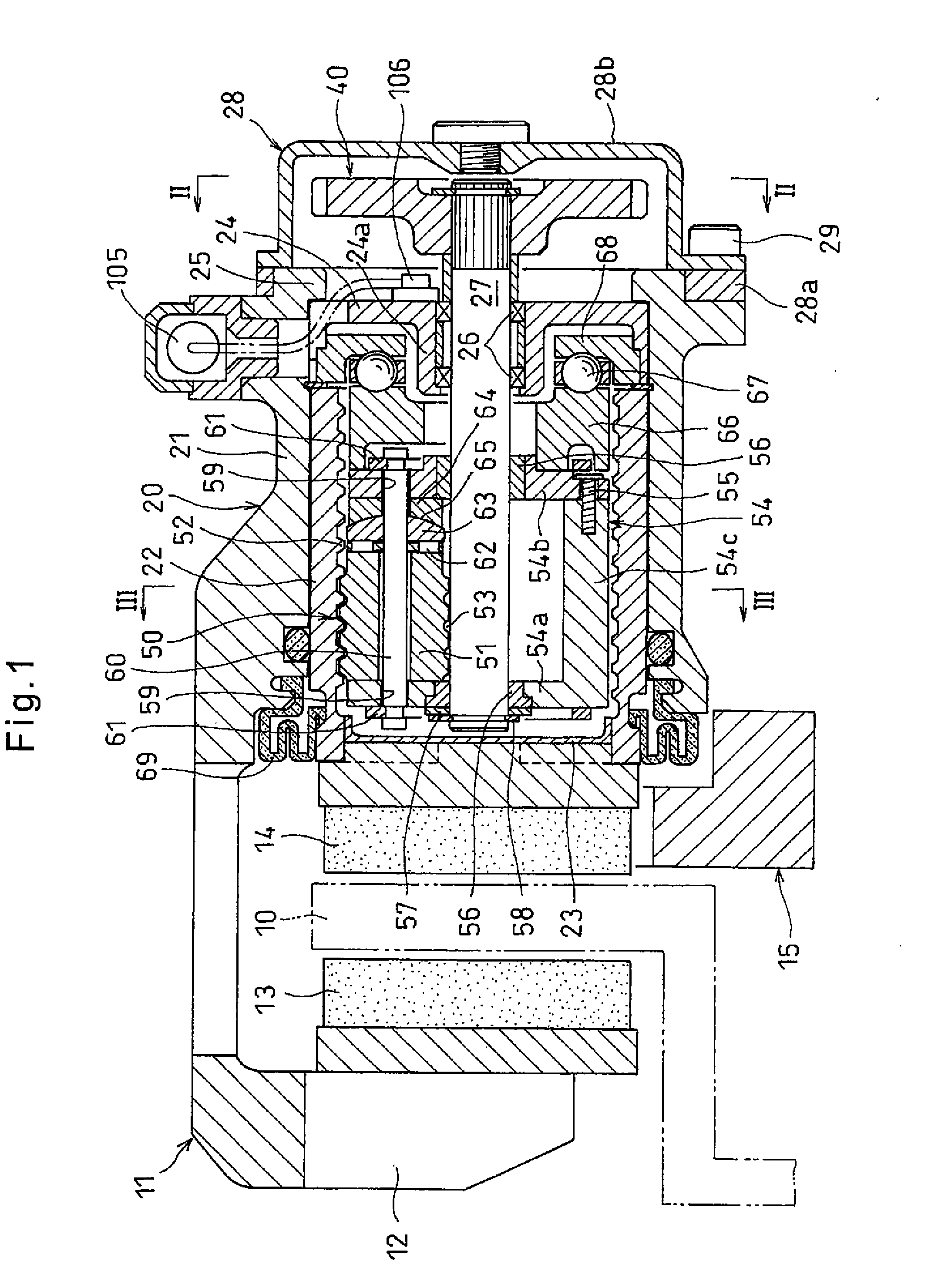
[0039]The embodiment of the present invention is now described with reference to the drawings. As illustrated in FIGS. 1 and 2, the electric brake system of the embodiment includes a caliper 11 provided so as to surround the outer periphery of a disk rotor 10 configured to rotate together with a wheel (not shown), and having a claw portion 12 provided at one end portion of the caliper 11 so as to be axially opposed to the outer peripheral portion of the outboard side surface of the disk rotor 10, and an outboard brake pad 13 supported by the claw portion 12.

[0040]The electric brake system further includes an inboard brake pad 14 arranged so as to be opposed to the outer peripheral portion of the inboard side surface of the disk rotor 10, and an electric linear motion actuator 20 provided at the other end portion of the caliper 11 and configured to move the inboard brake pad 14 toward the disk rotor 10.

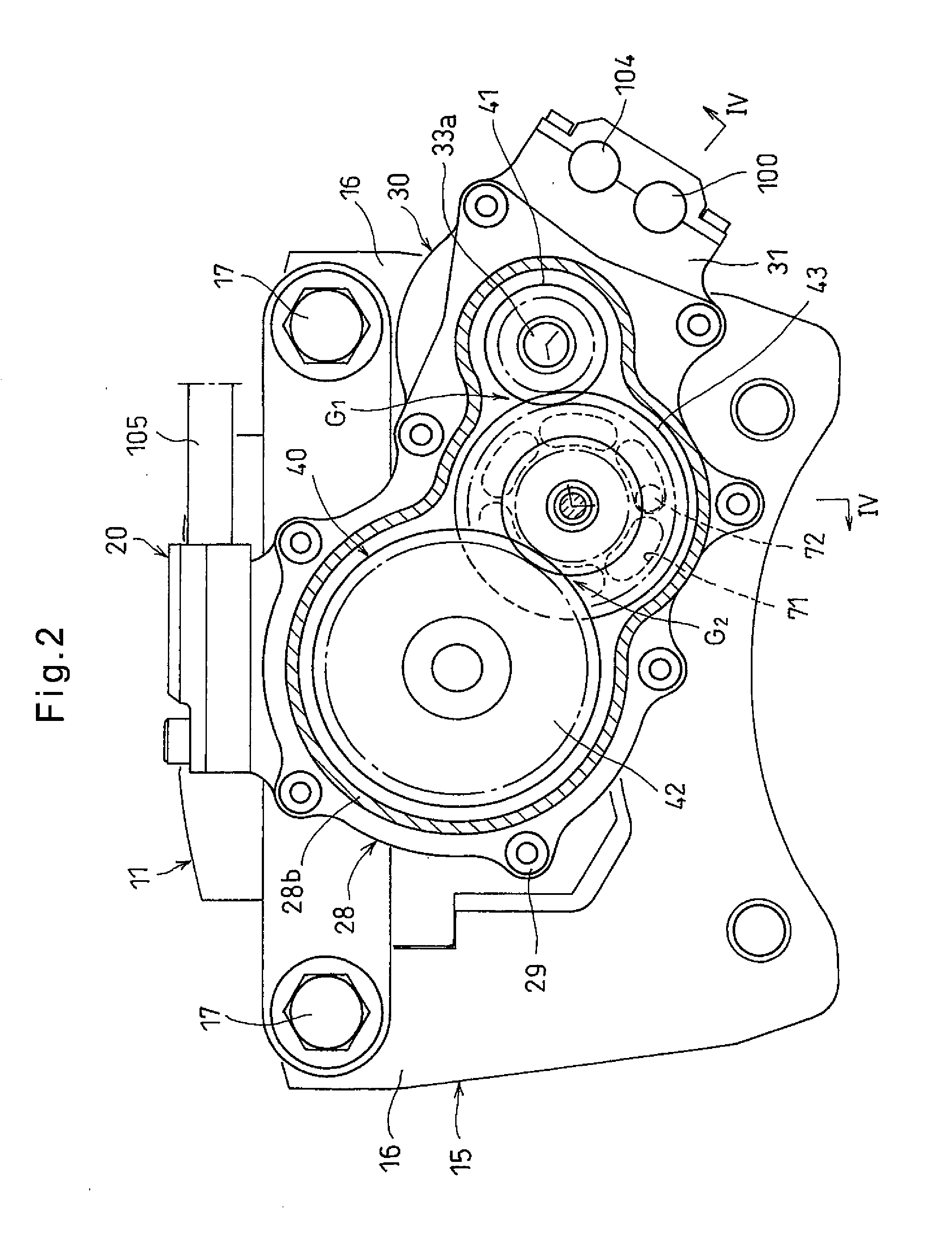
[0041]A mount 15 is provided near the outer peripheral portion of the disk rotor 1...


PUM


Abstract

The electric linear motion actuator includes an electric motor, a drive shaft configured to be rotated by the electric motor, a rotation-to-linear motion converting mechanism configured to convert the rotational motion of the drive shaft to the axial linear motion of an axially movably supported outer ring member, and an electric locking mechanism incorporated in a reduction gear mechanism in which the rotation of a rotor shaft of the electric motor is reduced in speed and transmitted to the drive shaft. When the electric locking mechanism is energized, the power transmission path shifts to the locked state in which power cannot be transmitted, and when the electric locking mechanism is de-energized thereafter, the power transmission path is kept in the locked state. The electric locking mechanism is built in a motor case of the electric motor so that the electric motor and the electric locking mechanism are unitized.

Description

TECHNICAL FIELD[0001]The present invention relates to an electric linear motion actuator for linearly driving a driven member such as a brake pad, and to an electric brake system in which this electric linear motion actuator is used.BACKGROUND ART[0002]As electric linear motion actuators of this type including an electric motor as a driving source, electric linear motion actuators as disclosed in the below-identified Patent documents 1 and 2 are known.[0003]In the electric linear motion actuators disclosed in Patent documents 1 and 2, planetary rollers are incorporated between a rotary shaft configured to be rotated by an electric motor and an axially movably supported outer ring member, when the rotary shafts rotates, the respective planetary rollers rotate about their axes while revolving around the rotary shaft due to the frictional contact of the planetary rollers with the rotary shaft, and a helical rib formed on the inner diameter surface of the outer ring member engages in a ...

Claims


Application Information

Patent Timeline
IPC IPC(8): F16D65/18F16H25/22F16H25/24F16D55/225
CPCF16D65/18F16D55/225F16D2125/50F16H25/2454F16D2121/24F16H25/2252H02K7/06H02K7/116F16D65/183
Inventor YAMASAKI, TATSUYAMURAMATSU, MAKOTOMASUDA, YUI
Owner NTN CORP
Why Eureka
Try Eureka