Systems, methods and articles for reading highly blurred machine-readable symbols

a machine-readable symbol and blurred image technology, applied in the field of reading or decoding machine-readable symbols, can solve the problems of reducing the quality of an image depicting machine-readable symbols, image blurring, and shutter speed being too slow or too fas

Active Publication Date: 2016-05-05
DATALOGIC IP TECH
View PDF0 Cites 17 Cited by
  • Summary
  • Abstract
  • Description
  • Claims
  • Application Information

AI Technical Summary

Benefits of technology

The patent describes a method and system for identifying machine-readable symbols in images. The method involves receiving training images with known machine-readable symbols, generating a distortion model based on the training images, and then creating a set of transformed distorted image signals based on the distortion model and the training images. These transformed distorted image signals are then used to extract classification features, which are used to train a machine-readable symbol classifier. The system includes a processor and a non-transitory storage medium that stores the training images and the distortion model. The technical effect of this patent is to provide a reliable and accurate method for identifying machine-readable symbols in images, which can be used in various applications such as image processing and machine-readable symbol recognition.

Problems solved by technology
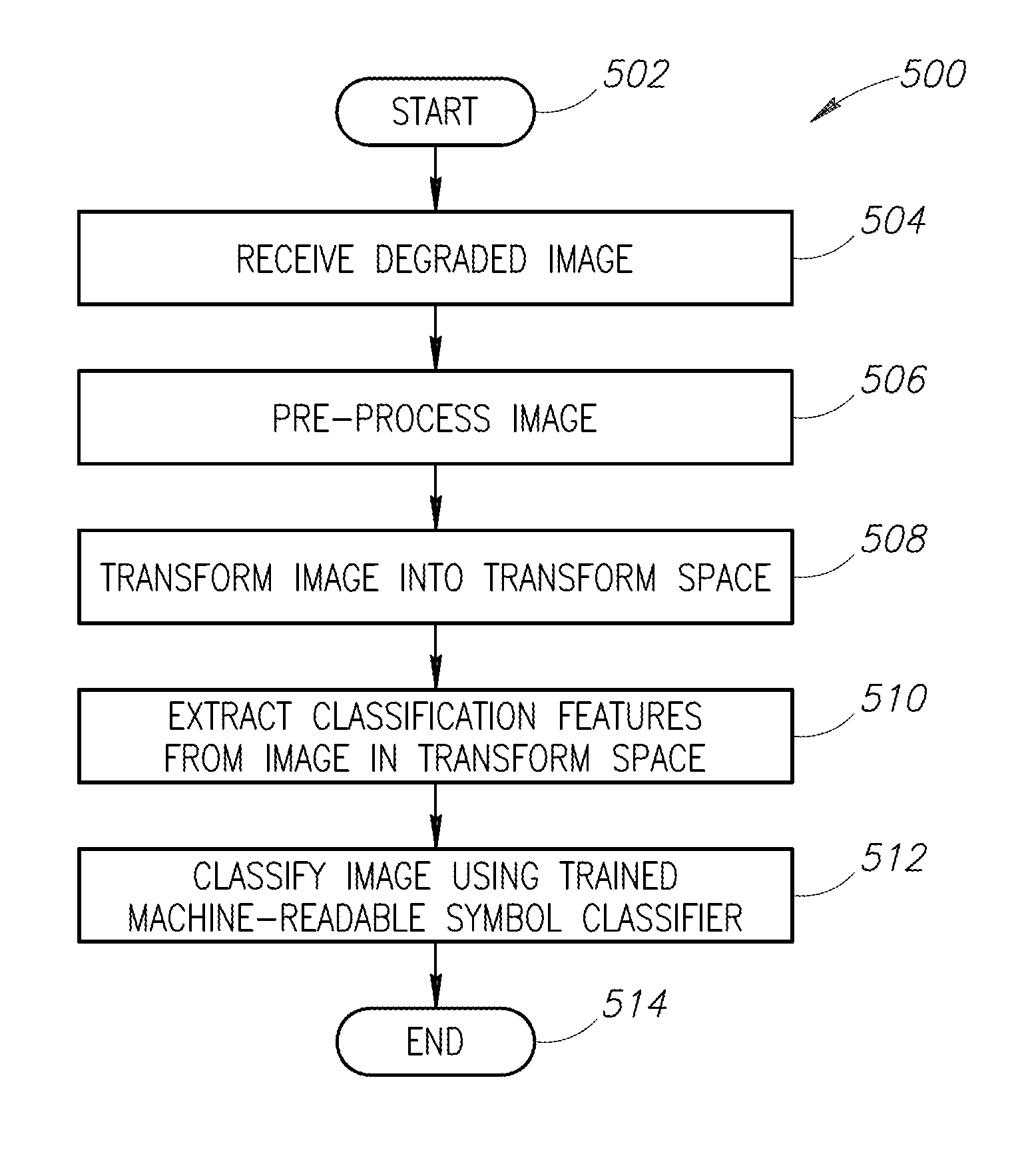
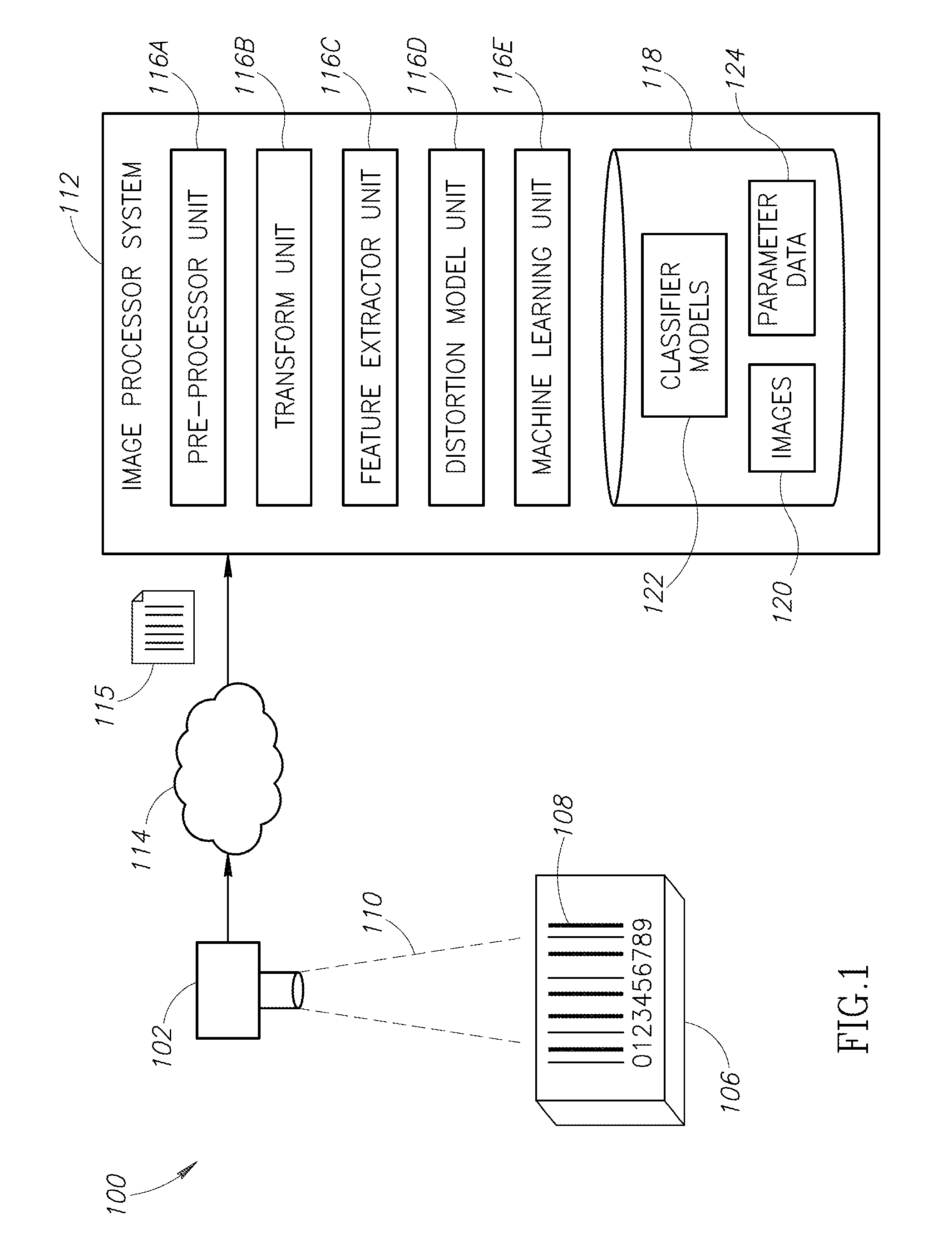
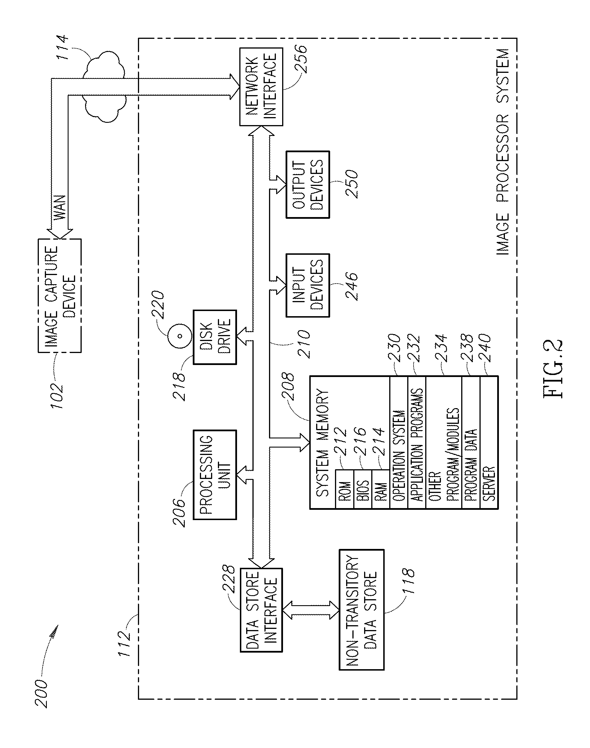
Noise and blur can reduce the quality of an image depicting a machine-readable symbol.
An image can be blurred because, for example, the image capture device used to capture the image was out of focus, the image capture device moved while the image was being captured, the object including the machine-readable symbol moved while the image was being captured, the shutter-speed was too slow or too fast for the light conditions, the lens of the image capture device was dirty, etc.
Using conventional techniques, decoding machine-readable symbols from highly blurred or distorted images can be difficult or impossible.

Method used


Image

  • Systems, methods and articles for reading highly blurred machine-readable symbols
  • Systems, methods and articles for reading highly blurred machine-readable symbols
  • Systems, methods and articles for reading highly blurred machine-readable symbols

Examples


Embodiment Construction

[0023]In the following description, certain specific details are set forth in order to provide a thorough understanding of various disclosed embodiments. However, one skilled in the relevant art will recognize that embodiments may be practiced without one or more of these specific details, or with other methods, components, materials, etc. In other instances, well-known structures associated with the various embodiments have not been shown or described in detail to avoid unnecessarily obscuring descriptions of the embodiments.

[0024]Unless the context requires otherwise, throughout the specification and claims that follow, the word “comprise” and variations thereof, such as, “comprises” and “comprising” are to be construed in an open, inclusive sense, that is as “including, but not limited to.”

[0025]Reference throughout this specification to “one embodiment” or “an embodiment” means that a particular feature, structure or characteristic described in connection with the embodiment is ...


PUM


Abstract

Systems and methods for robust recognition of machine-readable symbols from highly blurred or distorted images. An image signal representation of a machine-readable symbol element is transformed into a different space using one or more transform operations, which moves an n-dimensional vector of measured light intensities into another n-dimensional space. The types of transform operations may include blur robust orthonormal bases, such as the Discrete Sine Transform, the Discrete Cosine Transform, the Chebyshev Transform, and the Lagrange Transform. A trained classifier (e.g., an artificial intelligence machine learning algorithm) may be used to classify the transformed signal in the transformed space. The types of trainable classifiers that may be used include random forest classifiers, Mahalanobis classifiers, support vector machines, and classification or regression trees.

Description

BACKGROUND[0001]1. Technical Field[0002]The present disclosure relates to reading or decoding machine-readable symbols.[0003]2. Description of the Related Art[0004]Machine-readable symbols encode information in a form that can be optically read via a machine-readable symbol reader or scanner. Machine-readable symbols take a variety of forms, the most commonly recognized form being the linear or one-dimensional barcode symbol. Other forms include two-dimensional machine-readable symbols such as stacked code symbols, and area or matrix code symbols. These machine-readable symbols are typically made of patterns of high and low reflectance areas. For instance, a one-dimensional barcode symbol may comprise a pattern of black bars on a white background. Also for instance, a two-dimensional symbol may comprise a pattern of black marks (e.g., bars, squares or hexagons) on a white background. Machine-readable symbols are not limited to being black and white, but may comprise two other colors...

Claims


Application Information

Patent Timeline
Patent Type & Authority Applications(United States)
IPC IPC(8): G06K7/14G06V30/224
CPCG06K7/1473G06V30/2247G06V10/431
Inventor DEPPIERI, FRANCESCODE GIROLAMI, MAURIZIO ALDOLANZA, ALESSANDROSGALLARI, FIORELLA
Owner DATALOGIC IP TECH
Why Eureka
Try Eureka