
Touch down monitoring of an ocean bottom seismic node

a technology of seismic nodes and ocean bottom, which is applied in seismology, geological measurements, special purpose vessels, etc., can solve the problems of high cost of transponders, limited communication with transponders, and many problems with the use of transponders

Active Publication Date: 2016-05-05
SEABED GEOSOLUTIONS
View PDF1 Cites 46 Cited by
  • Summary
  • Abstract
  • Description
  • Claims
  • Application Information

AI Technical Summary

Benefits of technology

This patent describes a system and method for guiding and positioning seismic nodes on the seabed. An underwater vehicle monitors the deployment of a cable connected to the nodes, and a surface vessel controls a steering system and communicates with the underwater vehicle in real-time. The underwater vehicle can also track the position of the nodes and the cable, and the surface vessel can modify the position of the cable and nodes based on the underwater vehicle's communications. The technical effects of this patent include improved accuracy in the deployment of seismic nodes and better control over their positions.

Problems solved by technology

However, many problems exist with the use of transponders.
Because transponders are expensive, they are used infrequently on segments of the deployment cable, often at intervals of 300 meters or more.
Further, communications using transponders is very limited and does not provide the needed accuracy or real-time communications ability to guide the positioning of the deployed cable as it is being deployed.
Still further, the use of transponders provides no clear evidence data that touchdown (i.e., the point of contact of a node to the seabed) has effectively occurred, particularly as to each node.
Different orientations and improper configurations inhibit the coupling of the seismic sensor to the seabed, providing poor or inaccurate data.
Still further, the deployment and retrieval of transponders requires additional equipment on the deployment vessel and additional time for the handling of such transponders.

Method used


Image

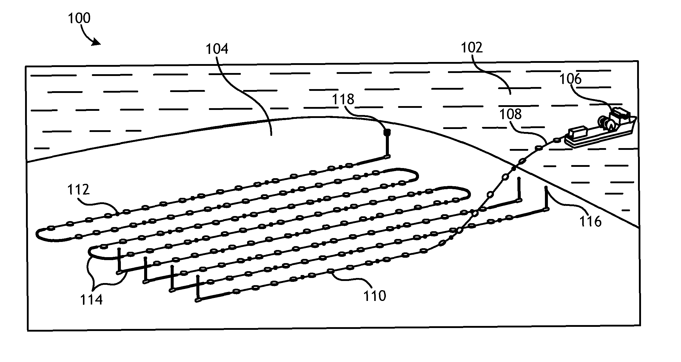
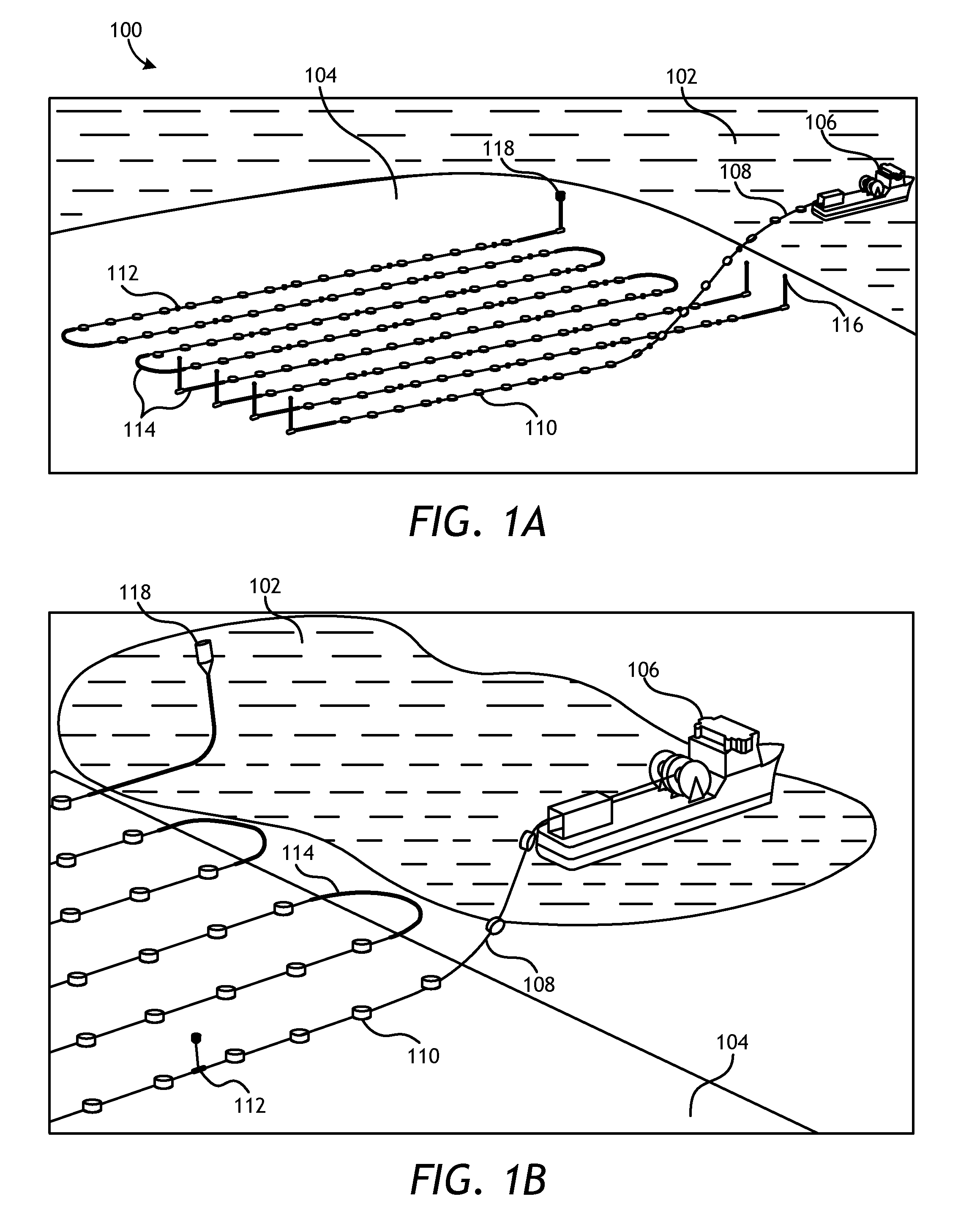
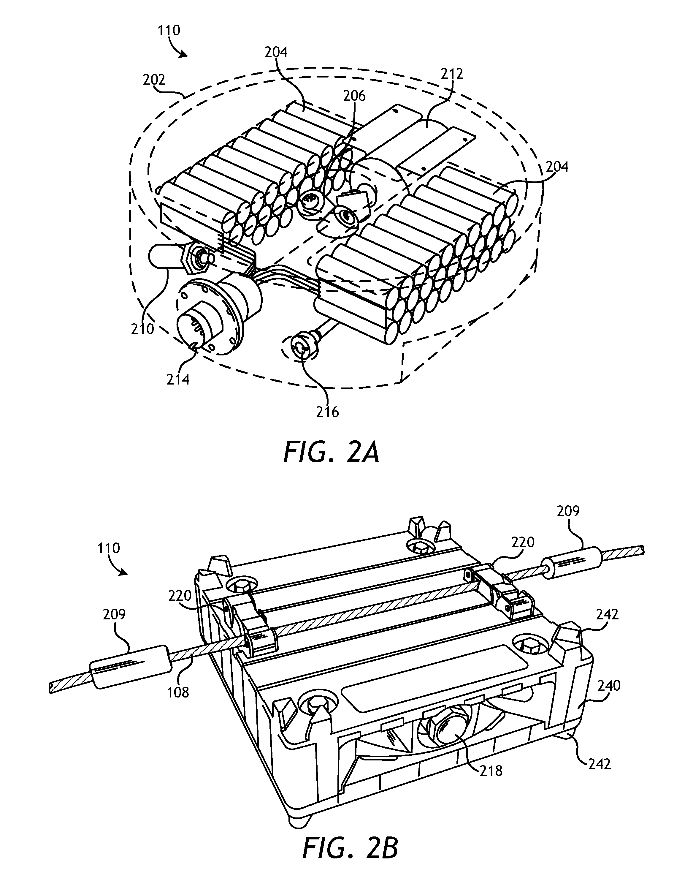
  • Touch down monitoring of an ocean bottom seismic node
  • Touch down monitoring of an ocean bottom seismic node
  • Touch down monitoring of an ocean bottom seismic node

Examples


Embodiment Construction

[0029]Various features and advantageous details are explained more fully with reference to the nonlimiting embodiments that are illustrated in the accompanying drawings and detailed in the following description. Descriptions of well known starting materials, processing techniques, components, and equipment are omitted so as not to unnecessarily obscure the invention in detail. It should be understood, however, that the detailed description and the specific examples, while indicating embodiments of the invention, are given by way of illustration only, and not by way of limitation. Various substitutions, modifications, additions, and / or rearrangements within the spirit and / or scope of the underlying inventive concept will become apparent to those skilled in the art from this disclosure. The following detailed description does not limit the invention.

[0030]Reference throughout the specification to “one embodiment” or “an embodiment” means that a particular feature, structure, or charac...


PUM


Abstract

Apparatuses, systems, and methods for guiding and / or positioning a plurality of seismic nodes on or near the seabed by an autonomous underwater vehicle (AUV) or a remotely operated vehicle (ROV). In one embodiment, an underwater vehicle is configured to monitor the deployment of cable connected to a plurality of seismic nodes, including the touchdown monitoring, positioning, and guiding of deployed autonomous seismic nodes or ocean bottom cable. The underwater vehicle may comprise a propulsion system configured to steer and propel the vehicle in a body of water, a tracking system configured to automatically track the cable and / or attached seismic nodes, and a guidance system configured to communicate with a surface vessel node data in real time or near real time for active guidance and / or positioning of the deployment cable.

Description

PRIORITY[0001]This application claims priority to U.S. provisional patent application No. 62 / 072,259, filed on Oct. 29, 2014, the entire content of which is incorporated herein by reference.BACKGROUND OF THE INVENTION[0002]1. Field of the Invention[0003]This invention relates to marine seismology and more particularly relates to the use of an underwater vehicle for the touchdown monitoring of the deployment of a plurality of ocean bottom seismic nodes.[0004]2. Description of the Related Art[0005]Marine seismic data acquisition and processing generates a profile (image) of a geophysical structure under the seafloor. Reflection seismology is a method of geophysical exploration to determine the properties of the Earth's subsurface, which is especially helpful in determining an accurate location of oil and gas reservoirs or any targeted features. Marine reflection seismology is based on using a controlled source of energy (typically acoustic energy) that sends the energy through seawate...

Claims


Application Information

Patent Timeline
Patent Type & Authority Applications(United States)
IPC IPC(8): G01V1/38
CPCG01V1/3835G01V1/3852B63G8/001
Inventor VALSVIK, GEIRROKKAN, ARNE HENNINGDANRE, JEAN-BAPTISTEISFELDT, BJARNE
Owner SEABED GEOSOLUTIONS
Learn More