Centering Bell Quick Change System

Active Publication Date: 2016-05-05
BEVCORP
View PDF10 Cites 0 Cited by
  • Summary
  • Abstract
  • Description
  • Claims
  • Application Information

AI Technical Summary

Benefits of technology

The present invention is a system that allows for quick and easy replacement of centering bells and CIP assemblies on can filling valves. It provides a fast connect / disconnect system that reduces downtime and allows for easy maintenance. The system includes a multiplier size adapter for bells and a quick change CIP assembly for easier connection and disconnection. The bells have a surface that makes it easier to attach and disconnect them to the adapter. The system is constructed of stainless steel for long use.

Problems solved by technology

A problem exists in that changing the bells requires stopping the line for a considerable amount of time to disconnect or unscrew all of the bells and reconnect the appropriate bells for the new can size.
For a filler having multiple valves (for example, 72), the time required to change each centering bell consumes valuable time that reduces production time.
Over torqueing can ruin the screw threads of the bell.
Removing each bell and connecting the cup to each valve is time consuming—taking many hours to remove each bell, attach each cup, remove the cup and reattach the bell to run a product.

Method used


Image

  • Centering Bell Quick Change System
  • Centering Bell Quick Change System
  • Centering Bell Quick Change System

Examples


Embodiment Construction

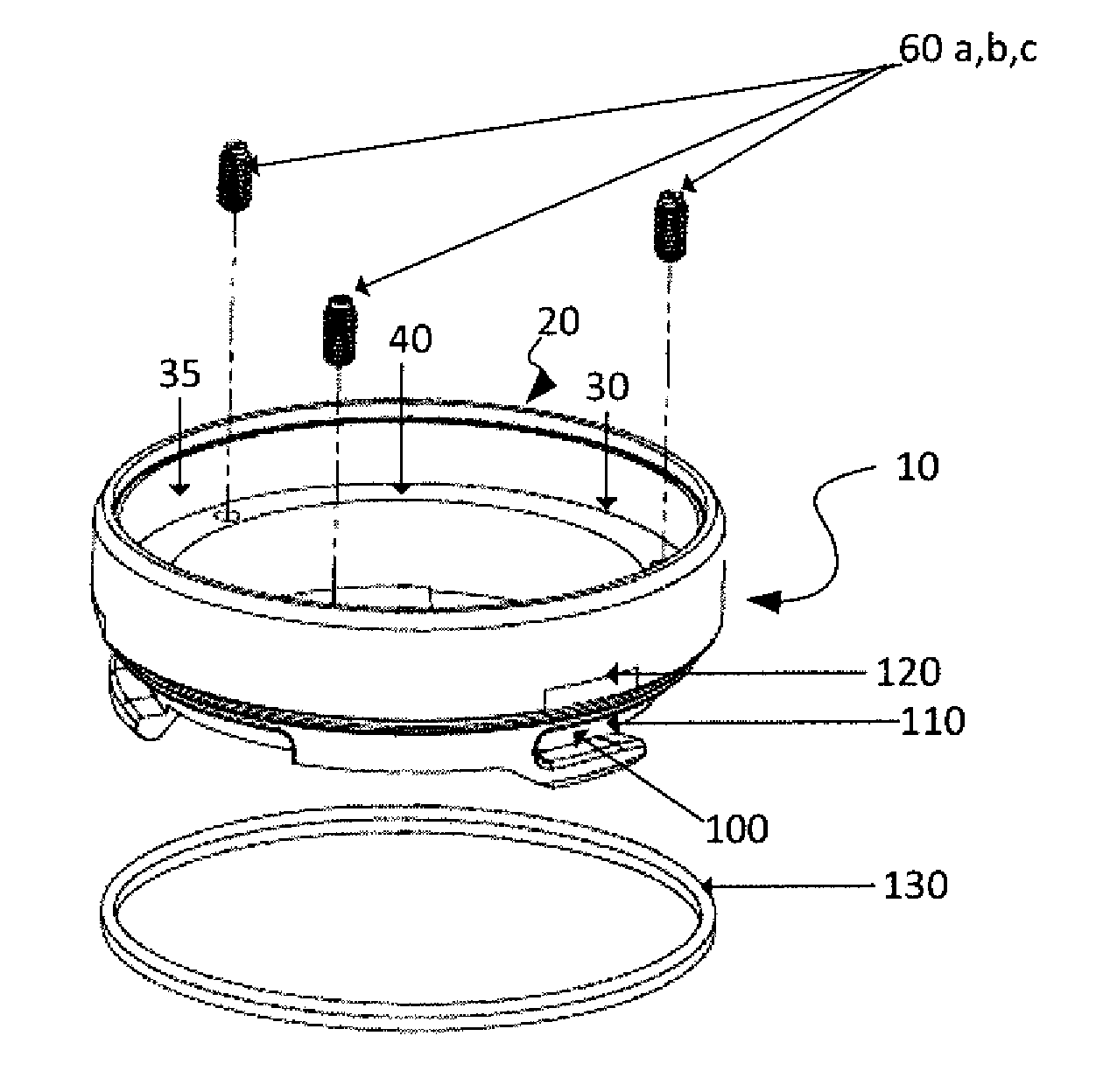
[0046]The disclosure is directed to a quick connect / disconnect system that allows beverage can filling valve centering bells and CIP assemblies to be connected / disconnected quickly and easily when running a different size can or cleaning an automated filling line.

[0047]Referring now to the drawings, FIG. 1 illustrates a first embodiment of the adapter 10 for attaching to a beverage filling valve. The adapter has a cylindrical shape with a top opening 20 adapted to connect and disconnect to a lower portion of the valve housing that typically receives a centering bell. In an embodiment, the top opening connects to the valve by screw threads on an internal wall 35. The adapter connects to the housing in a water-tight fashion.

[0048]The adapter comprises an annular collar 30 at the end of the threads defining the mouth of the adapter. The collar comprises an inwardly directed rim 40 formed therein extending completely around the interior wall of the adapter.

[0049]The adapter comprises at...


PUM

PropertyMeasurementUnit
Forceaaaaaaaaaa
Diameteraaaaaaaaaa

Abstract

An adapter system for a beverage can filling valve for quick connection / disconnection of multiple centering bells used to fill differently sized cans and a CIF assembly.

Description

CROSS-REFERENCE TO RELATED APPLICATIONS[0001]This application claims the priority benefit of U.S. provisional patent application No. 62 / 073,333 filed on Oct. 31, 2014, the disclosure of which is expressly incorporated herein in its entirety by reference.TECHNICAL FIELD[0002]The invention relates to an adapter system for an automatic beverage filling machine for quickly attaching and detaching differently sized centering bells and clean in place devices.BACKGROUND[0003]Beverage cans are sometimes filled by automated container filling systems. In such a system, an empty can is engaged with a filling valve creating a seal and the beverage dispensed from a pressurized tank through the valve and into the can. In the filling process, a plurality of cans move in a line through a rotary filler having multiple valves. Empty cans are presented to each filling valve as the rotary filler turns. The empty cans must be correctly centered beneath the filling valve to avoid damage to the can, foami...

Claims


Application Information

Patent Timeline
IPC IPC(8): B67C3/26B67C3/00B67C3/22
CPCB67C3/26B67C3/225B67C2003/266B67C2003/2657B67C2003/2668B67C3/002
Inventor SWEENY, KEVINSAMAROO, RISHIERAM
Owner BEVCORP
Why Eureka
Try Eureka