Rod clamp

Inactive Publication Date: 2005-07-05
WEISS SONDRA
View PDF19 Cites 14 Cited by
  • Summary
  • Abstract
  • Description
  • Claims
  • Application Information

AI Technical Summary

Benefits of technology

[0007]It is also an objective to provide a light weight clamp which is easy to adjust linearly and angularly, yet which is reliable and secure once set in position.
[0008]Another object it to provide a hand-held rod holder which can be changed quickly and easily between right-handed and left-handed configurations.

Problems solved by technology

Some of the equipment which is attached to a bed for patient transportation may be very expensive; partly for that reason, it is very important that the connection between a supporting pole and the fixture be secure.
Various types of clamps have been adapted to connect supporting rods to fixtures such as hospital beds, but none is sufficiently adaptable and easy to use.
Generic clamps are difficult to manipulate.

Method used


Image

  • Rod clamp
  • Rod clamp
  • Rod clamp

Examples


Embodiment Construction

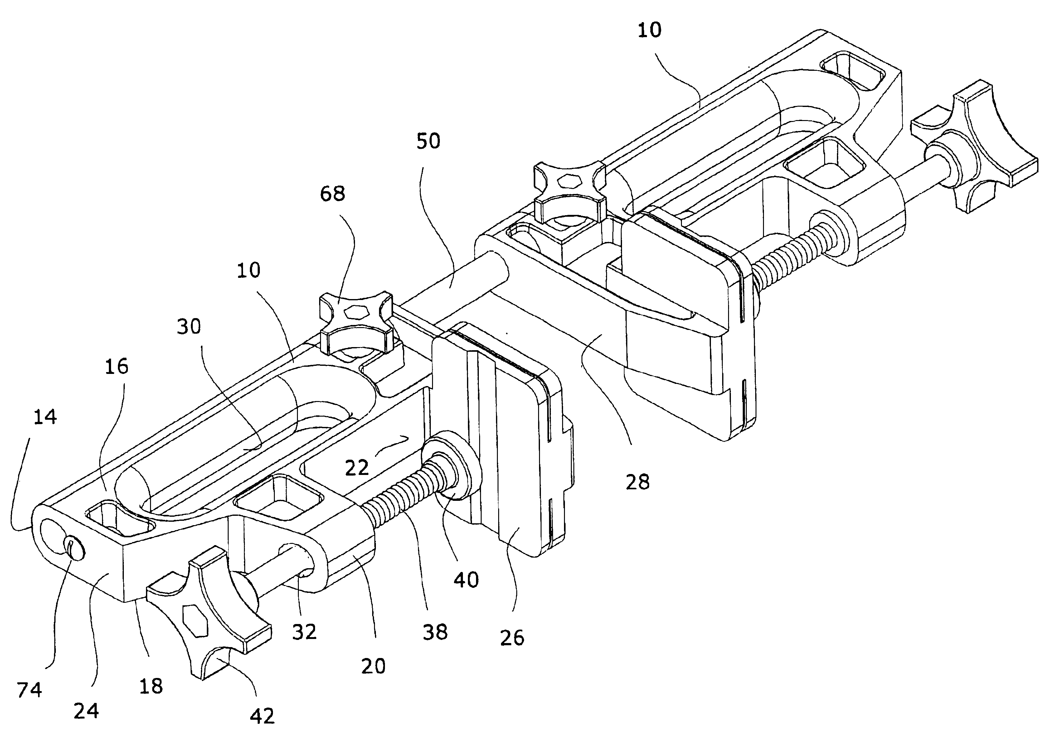
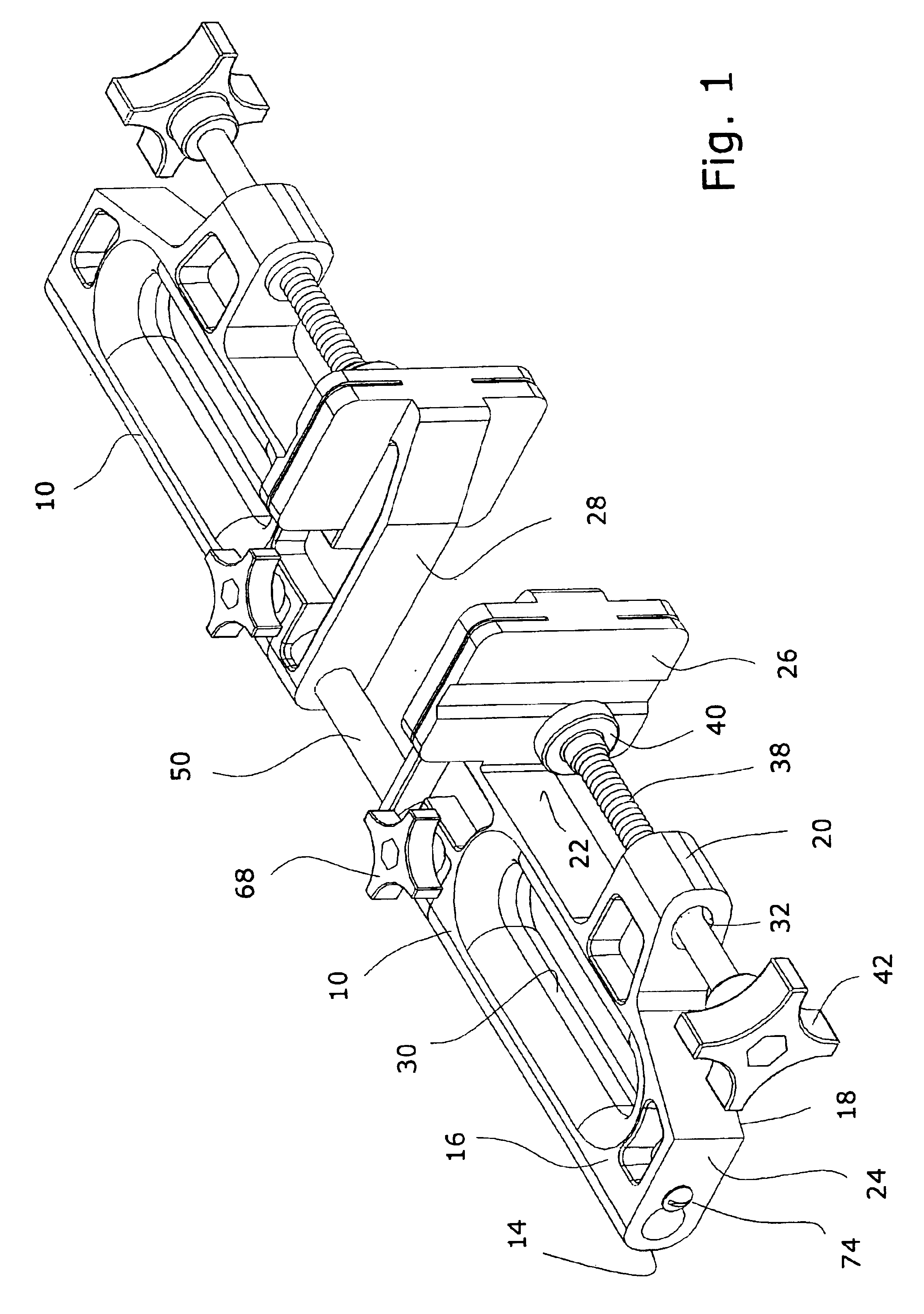
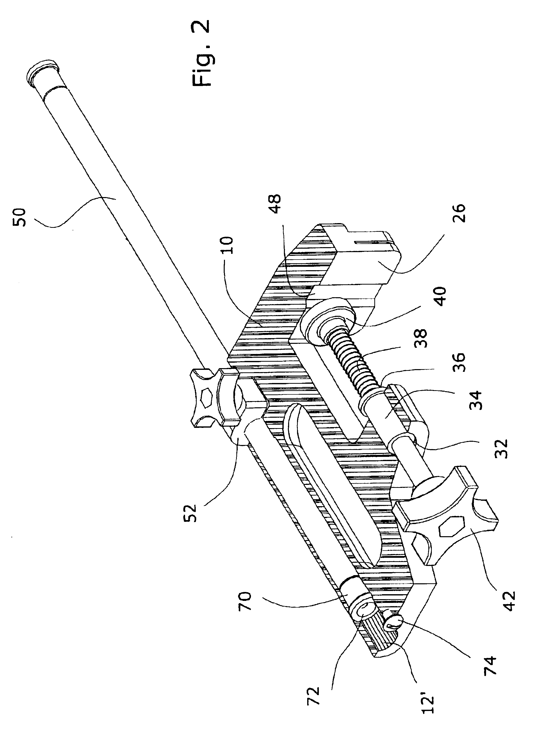
[0014]Each of the rod holders shown in FIG. 1 comprises a body 10 molded from a hard polymeric material. The body has a through bore 12 (FIG. 2) extending lengthwise parallel to and just below the top surface 14 (FIG. 1) of the body. The body is bounded by parallel right and left sides 16, 18. A boss 20 protrudes downward from the bottom surface 22 of the body, near its rear end 24. A fixed jaw 26 extends from the bottom surface at the front end 28 of the body

[0015]A large elongate slot 30 passes transversely through the body. Its edges are rounded to provide a comfortable hand hold.

[0016]The boss has a hole 32 (FIG. 2), counterbored at the front. The hole's axis is preferably parallel to that of the bore 12. A metal insert 34 is seated in the hole 32. The insert has a shoulder 36 at the front to prevent the insert from being pushed rearward. The insert is internally threaded and receives a clamping screw 38 whose front end supports a polymeric pad 40. By turning a handle 42 fixed t...


PUM


Abstract

A rod is gripped by a clamp which is removably seated in a lateral recess in a hand-held rod holder. The clamp is tightened around the rod by turning a threaded actuator. The holder configuration is easily changed from right-handed to left-handed by removing the rod and reversing the clamp in its recess. The body of the holder has a fixed jaw, and a separate movable jaw is provided so one can secure the body to a fixture such as a hospital bed. When a pair of the rod holders are mounted at opposite ends of a common rod, they can be adjusted along the rod, and angularly about the rod with respect to each other, thus forming a versatile clamping system for temporarily linking diverse objects.

Description

[0001]This application is a continuation-in-part of application Ser. No. 10 / 265,897, filed Oct. 7, 2002, now U.S. Pat. No. 6,688,569.BACKGROUND OF THE INVENTION[0002]This invention relates to an improved holder for securing a rod to a fixture, and for permitting adjustment of the rod's height and orientation. The invention also relates to a clamping system in which two holders, situated on a common rod, are attached to ordinarily separate objects to provide an adjustable, secure, yet temporary connection between them.[0003]The need for temporarily interconnecting movable objects occurs in many different environments. For example, in a hospital, when a patient must be moved to a different room, it is usually necessary simultaneously to move I.V. poles, monitoring devices and other equipment attached to the patient. In complex procedures, such as heart transplantation, three or four poles, each supporting a different device, may be needed. The number of people needed to make the move ...

Claims


Application Information

Patent Timeline
IPC IPC(8): A47B23/00A47B23/02B25B5/00B25B5/10F16M13/02A61G5/00A61G5/10A61G7/05A63B55/08A63B55/60
CPCF16M13/02B25B5/003B25B5/10B25B5/102F16M13/022B62B2207/00A47B23/02A61G5/10A61G7/05A61G2203/80A63B2055/083A63B2055/603
Inventor WEISS, SONDRA
Owner WEISS SONDRA
Why Eureka
Try Eureka