Method for defining fiber trajectories from curves or constraint grid
a technology of constraint grid and fiber trajectories, applied in special data processing applications, instruments, electric digital data processing, etc., can solve the problems of long and tedious definition of trajectories, unidirectional axis system, and a multitude of filaments, and achieve the effect of reducing the time for defining trajectories
- Summary
- Abstract
- Description
- Claims
- Application Information
AI Technical Summary
Benefits of technology
Problems solved by technology
Method used
Image
Examples
first embodiment
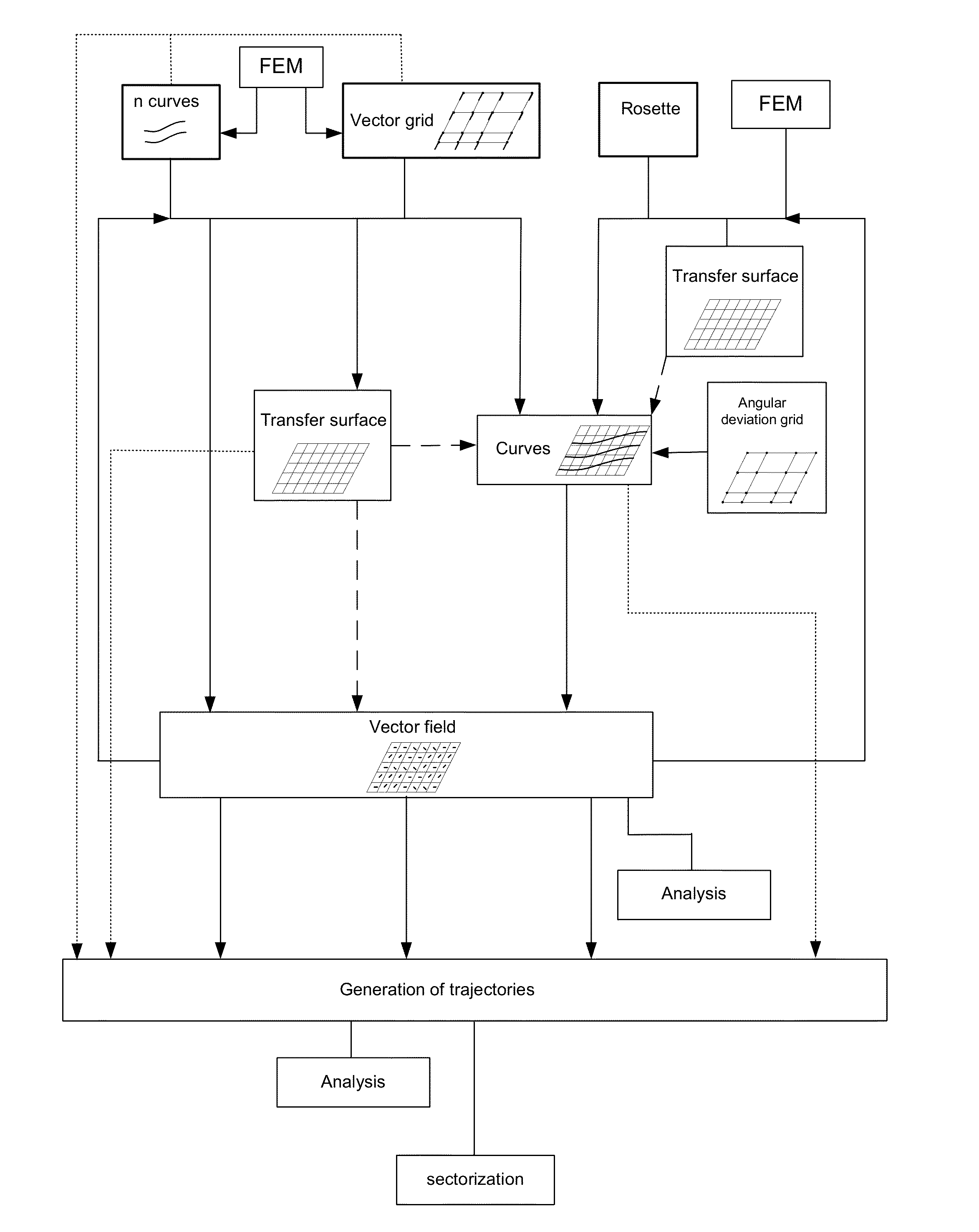
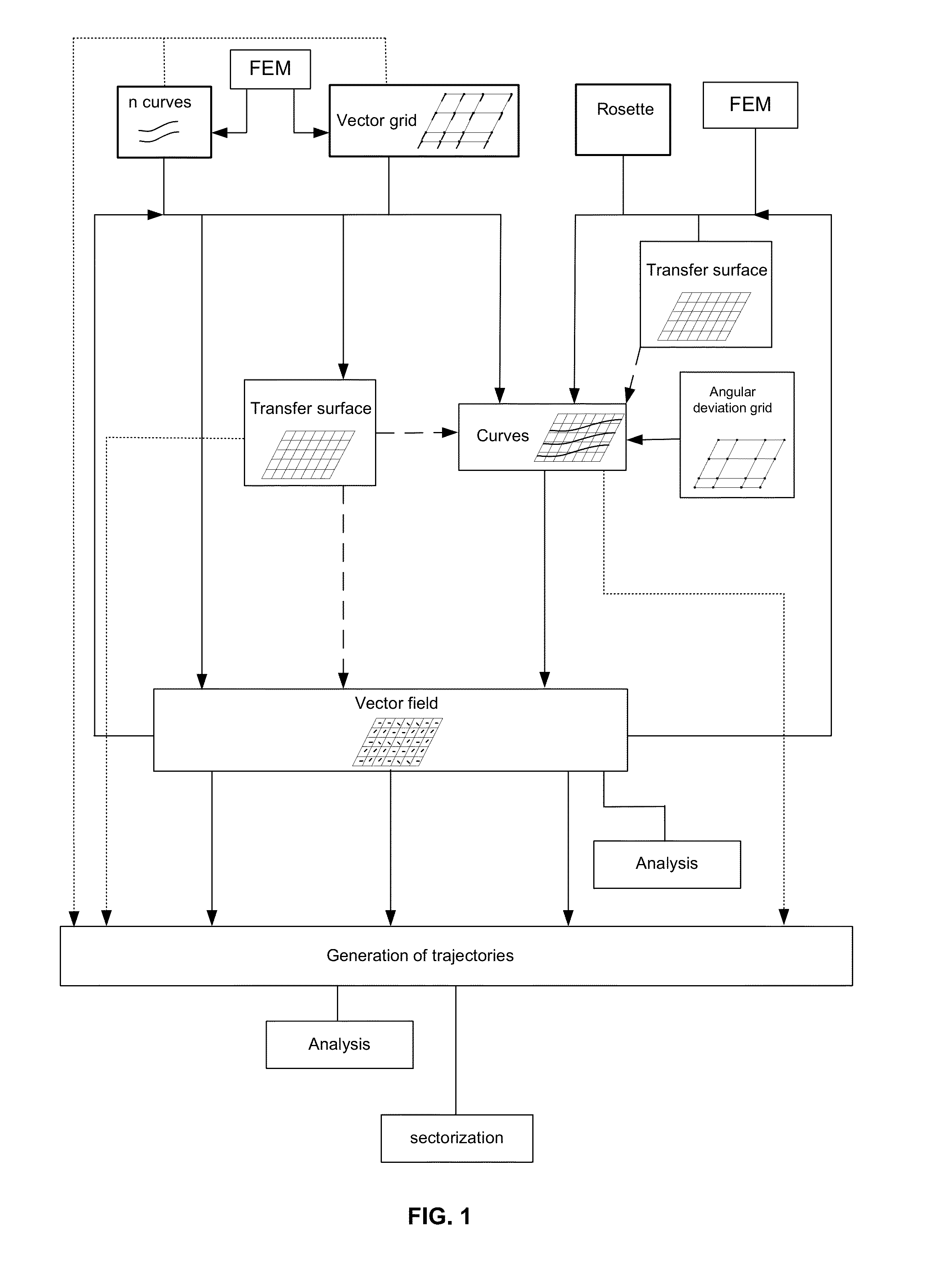
[0113]FIG. 8 illustrates the invention in which a vector field is obtained from a constraint grid, to take into account the design and / or manufacturing constraints within the definition of the trajectories, and thus obtain trajectories with an acceptable radius of curvature.
[0114]With reference to FIG. 9, one defines in the first instance a constraint grid 2, also called constraint vector grid. In this example, the constraint grid is defined according to the geometric constraints of the layup surface, here the geometric constraints being the following:[0115]the fibers of the ply at 0° must follow the generatrix line 92 of the connecting radii between the globally frustoconical central part of the layup surface and the planar parts on either side of said frustoconical part, and[0116]the fibers of the ply at 0° must be aligned with the outer edges 93 of the planar parts.
[0117]A mesh 21 is defined from these geometric constraints, each element of the mesh being formed of at least four ...
second embodiment
[0125]FIG. 15 illustrates a second embodiment in which a vector field is obtained from the constraint curves. Geometric constraints represented under the form of a constraint grid 2 in the previous embodiment are represented here under the form of constraint curves.
[0126]With reference to FIG. 16, the constraint curves, collectively referred to under reference 3, include:[0127]two linear constraint curves 31, 32 corresponding to the outside edges 93 of the layup surface, and[0128]two curved constraint curves 33, 34 corresponding to the generatrix lines of connecting radii between the central part and lateral parts of the layup surface.
[0129]To form the vector field, the direction vector of each element of the mesh is defined in the following manner.
[0130]Considering the central point P2 of an element on FIG. 16, one performs a normal projection of a central point P2, on the two closest constraint curves 31, 33, between which the central point is positioned. One then defines, at the ...
third embodiment
[0133]FIG. 17 illustrates a third embodiment in which a vector field is obtained from the constraint curves which are defined from an angular deviation grid.
[0134]With reference to FIG. 18, one defines in a first instance an angular deviation grid 4, in which each element is defined by four nodes N′, and one assigns to each node of the grid a maximum angular deviation value. An example of deviation values assigned to the different nodes is given in FIG. 18.
[0135]Constraint curves are generated on the layup surface by defining for each constraint curve the propagation directions at different points of analysis also called propagation points. The propagation direction at a propagation point P3 is defined in the following manner
[0136]With reference to FIG. 19, one defines a reference direction at the propagation point P3, this reference direction TR being in this embodiment a direction obtained by a Cartesian rosette, by transfer by normal projection of the vector X of the global roset...
PUM
| Property | Measurement | Unit |
|---|---|---|
| Weight | aaaaa | aaaaa |
| Angle | aaaaa | aaaaa |
Abstract
Description
Claims
Application Information
 - R&D
- Intellectual Property
- Life Sciences
- Materials
- Tech Scout
- Unparalleled Data Quality
- Higher Quality Content
- 60% Fewer Hallucinations
Browse by: Latest US Patents, China's latest patents, Technical Efficacy Thesaurus, Application Domain, Technology Topic, Popular Technical Reports.
© 2025 PatSnap. All rights reserved.Legal|Privacy policy|Modern Slavery Act Transparency Statement|Sitemap|About US| Contact US: help@patsnap.com


