
Plasma processing apparatus

a processing apparatus and plasma technology, applied in the direction of electric discharge tubes, coatings, chemical vapor deposition coatings, etc., can solve the problems of chamber damage and particle generation, and achieve the effect of suppressing abnormal discharg

Active Publication Date: 2016-04-28
TOKYO ELECTRON LTD
View PDF6 Cites 211 Cited by
  • Summary
  • Abstract
  • Description
  • Claims
  • Application Information

AI Technical Summary

Benefits of technology

The present invention aims to prevent abnormal discharge in a plasma processing apparatus by reducing the propagation of electromagnetic waves. The invention includes a plasma processing apparatus with a dielectric window, a support member, a partition member with a protrusion, and a conductive member between the partition member and the dielectric window. The conductive member is protected from exposure to the plasma generation space by the protrusion. The technical effect of this invention is to enhance the stability and safety of plasma processing.

Problems solved by technology

When abnormal discharge occurs within the chamber, the chamber may be damaged and particles may be generated from the chamber walls.

Method used


Image

  • Plasma processing apparatus
  • Plasma processing apparatus
  • Plasma processing apparatus

Examples


Embodiment Construction

[0018]In the following, embodiments of the present invention will be described with reference to the accompanying drawings. Note that in the following descriptions and drawings, elements having substantially the same features are given the same reference numbers and overlapping descriptions thereof may be omitted.

[0019][Overall Configuration of Plasma Processing Apparatus]

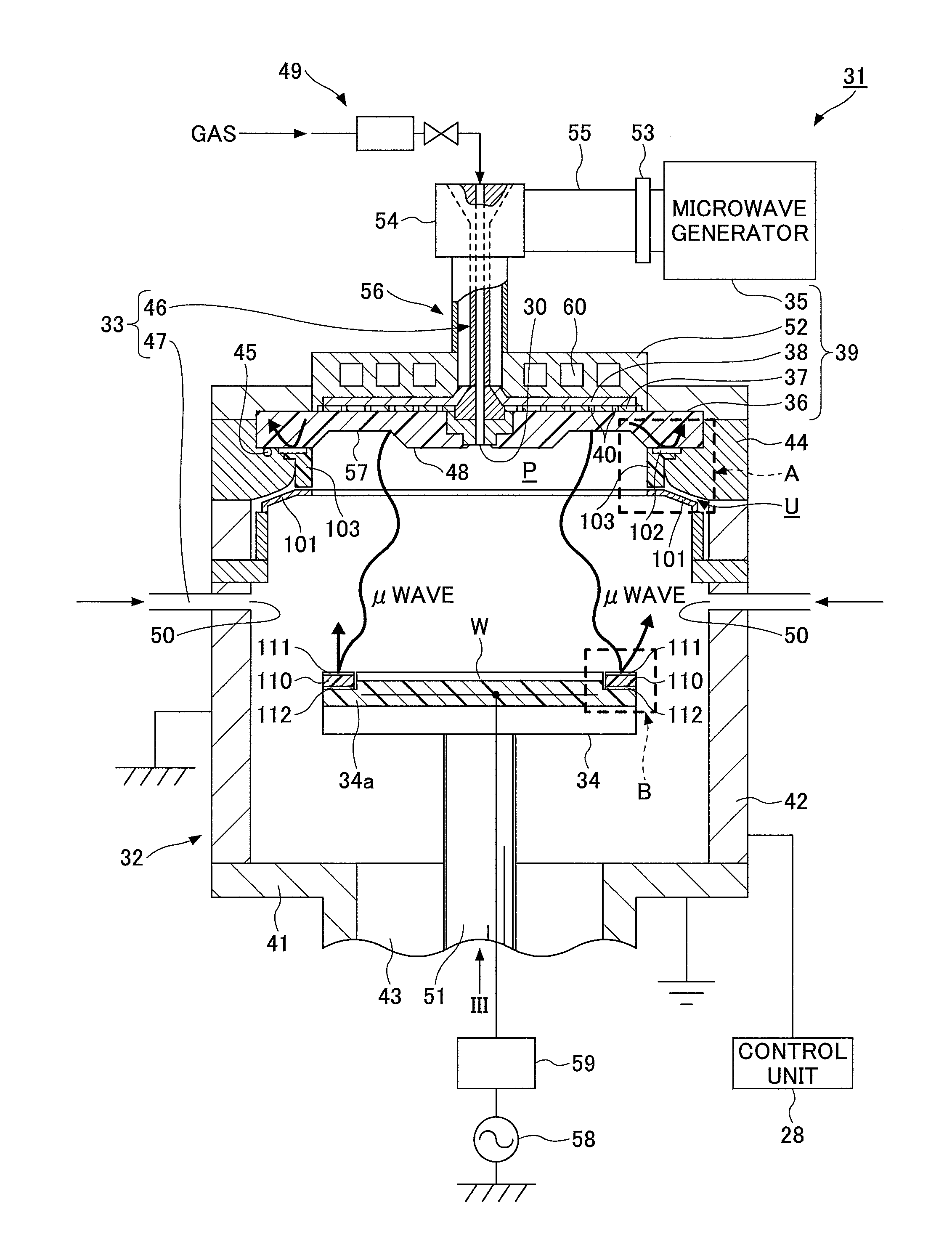
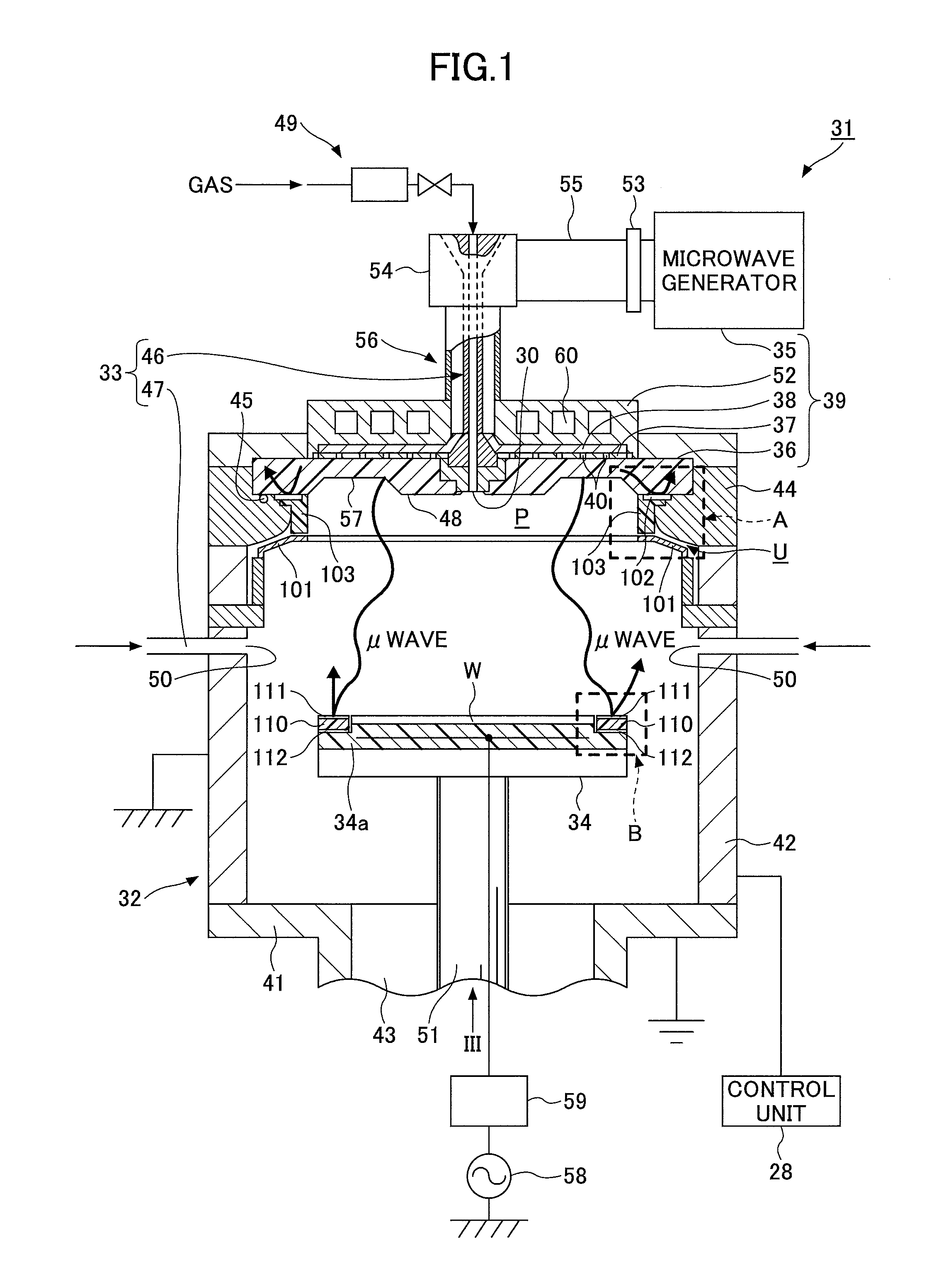
[0020]First, an overall configuration of a plasma processing apparatus 31 according to an embodiment of the present invention will be described with reference to FIG. 1. FIG. 1 is a cross-sectional view of the plasma processing apparatus 31 according to an embodiment of the present invention. In the present embodiment, a plasma processing apparatus using a radial line slot antenna is illustrated as an example of the plasma processing apparatus 31. Another example of the plasma processing apparatus 31 includes an electron cyclotron resonance (ECR) plasma apparatus. The plasma processing apparatus 31 may be any appar...


PUM

PropertyMeasurementUnit
Poweraaaaaaaaaa
Electrical conductoraaaaaaaaaa
Distanceaaaaaaaaaa

Abstract

A plasma processing apparatus is provided that is configured to supply a gas into a chamber, generate a plasma from the gas using a power of an electromagnetic wave, and perform a predetermined plasma process on a substrate that is held by a mounting table. The plasma processing apparatus includes a dielectric window through which the electromagnetic wave that is output from an electromagnetic wave generator is propagated and transmitted into the chamber, a support member that supports the dielectric window, a partition member that separates a space where the support member is arranged from a plasma generation space and includes a protrusion abutting against the dielectric window, and a conductive member that is arranged between the partition member and the dielectric window and is protected from being exposed to the plasma generation space by the protrusion.

Description

BACKGROUND OF THE INVENTION[0001]1. Field of the Invention[0002]The present invention relates to a plasma processing apparatus.[0003]2. Description of the Related Art[0004]Techniques are known for controlling the generation of plasma in a plasma processing apparatus that supplies a gas into a chamber, generates plasma from the gas using a high frequency power, and performs a predetermined plasma process on a substrate that is held by a mounting table.[0005]For example, Japanese Laid-Open Patent Publication No. 2001-185542 (Patent Document 1) discloses an apparatus including a current path correction means for correcting a part of a high frequency current path that is formed by a high frequency bias applied to a wafer and is near an outer periphery of the wafer, wherein the current path part is forced toward an opposing electrode surface facing the wafer. As an example of the current path correction means, a conductive member is disposed near a wall at a lower part of a dielectric bo...

Claims


Application Information

Patent Timeline
IPC IPC(8): H01J37/32
CPCH01J37/32009H01J37/3244H01J37/32192H01J37/32266H01J37/32944
Inventor KOHNO, MASAYUKISON, RYOUMATSUMOTO, NAOKIYOSHIKAWA, JUNAITA, MICHITAKASHIMIZU, IPPEIYOSHIDA, YUSUKEKOYAMA, KOJISUDAYAMA, MASAMIARAMAKI, YUKIYOSHI
Owner TOKYO ELECTRON LTD
Learn More