Thermal oscillator
a technology of thermal oscillator and oscillator, which is applied in the direction of heat measurement, instruments, optical radiation measurement, etc., can solve the problems of induced radial heat flux from heat sources, and achieve the effects of enhancing the efficiency of converters based on pyroelectric, pyromagnetic or piezoelectric effects, and enhancing the sensitivity of thermal sensing devices
- Summary
- Abstract
- Description
- Claims
- Application Information
AI Technical Summary
Benefits of technology
Problems solved by technology
Method used
Image
Examples
first embodiment
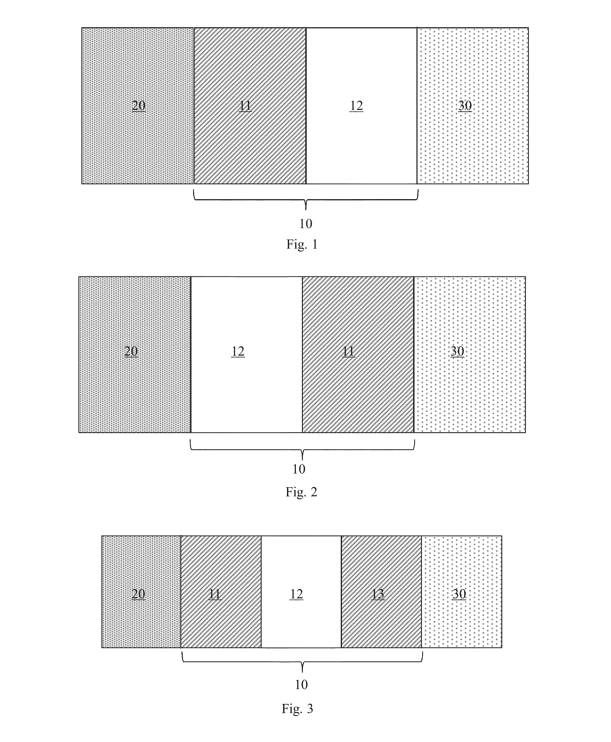
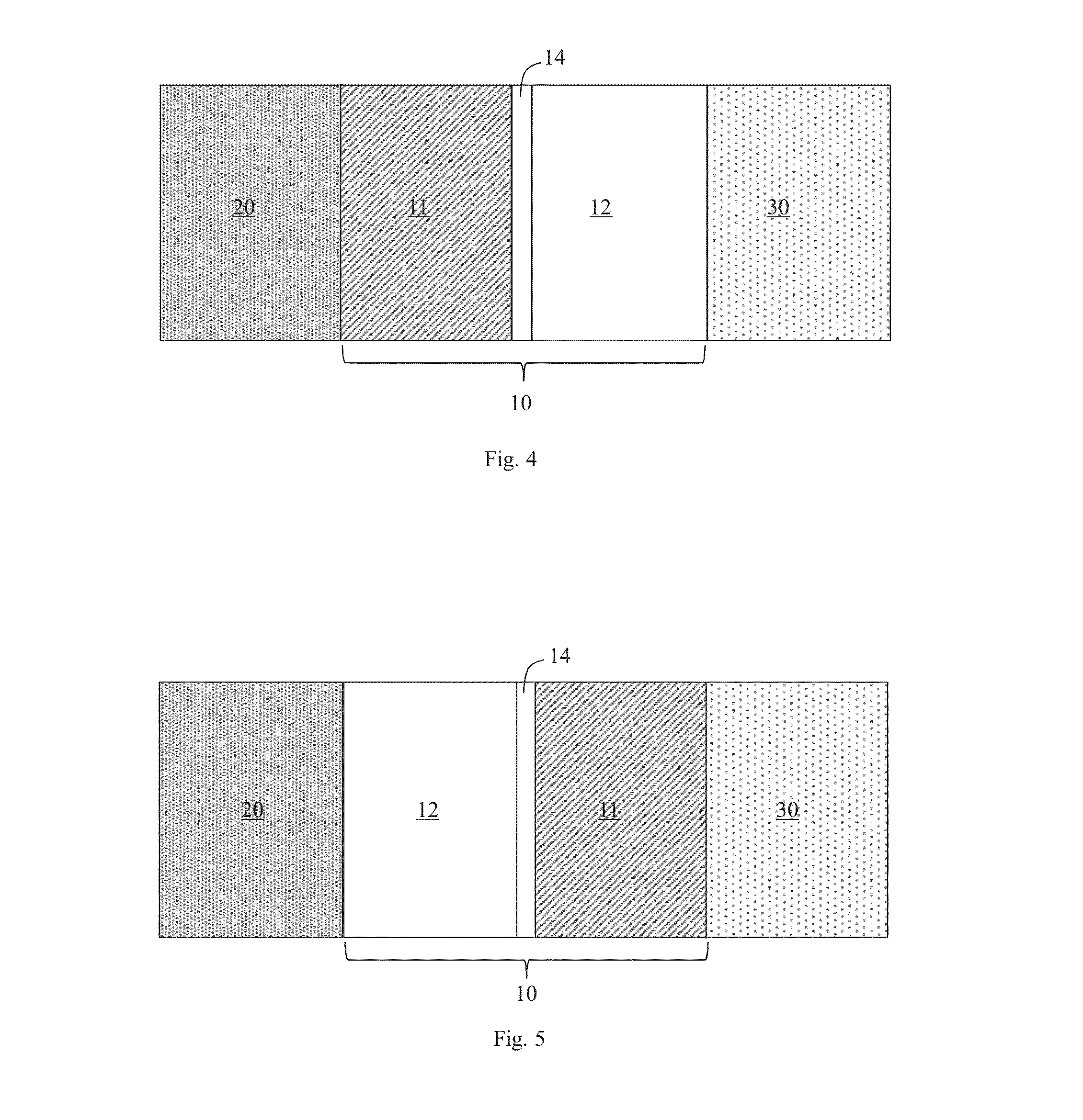
[0078]In FIG. 1, a schematic block diagram of a thermal oscillator 10 for creating an oscillating heat flux from a stationary spatial thermal gradient between a warm reservoir 20 and a cold reservoir 30 is depicted.
[0079]The thermal oscillator 10 comprises a thermal conductor 11 and a thermal switch 12. The thermal conductor 11 is configured to contact a heat flux from the warm reservoir 30 towards the cold reservoir 20.
[0080]The thermal switch 12 is coupled to the thermal conductor 11. In particular, the thermal switch 12 is connected to the thermal conductor 11. The thermal switch 12 is configured to receive the heat flux conducted by the thermal conductor 11. The thermal switch 12 has a certain difference between two states S1, S2 of thermal conductance, (see FIG. 8) for example due to metal-insulator phase transitions. In combination with the thermal conductor 11, alternating phase transitions are created leading to thermal relaxations such that the oscillating heat flux is crea...
third embodiment
[0087]FIG. 7 shows a schematic block diagram of a thermal oscillator 10 for creating an oscillating heat flux from a stationary spatial thermal ingredient between a warm reservoir 20 and a cold reservoir 30 and corresponding temperature profiles for the oscillator being in a stationary state slightly below and above the switching temperature interval H
[0088]The temperature T is shown as a function of position P along the thermal oscillator 10 for two possible stationary states. FIG. 7 shows that depending on the state S1 or S2 of the thermal switch 12 of the thermal oscillator 10, the temperature distribution T along the thermal oscillator 10 changes approaching the two “idle” steady states S1, S2, given by the relative thermal conductance values of the thermal switch 12 and the thermal conductors 11, 13.
[0089]In FIG. 8, the conductance k of the thermal switch 12 of FIG. 1 as a function of temperature T is depicted. The thermal switch 12 is configured to switch at a first switching ...
second embodiment
[0093]FIG. 9 shows the thermal conductance of a thermal switch 12 as a function of temperature as suitable for the thermal oscillator 10 of the
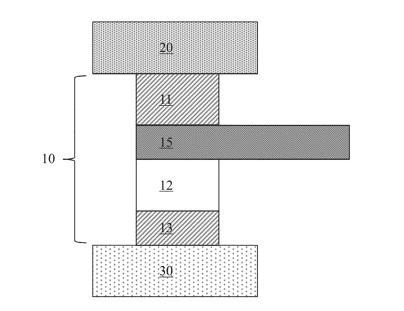
[0094]In FIG. 10, a schematic block diagram of a seventh embodiment of a thermal oscillator 10 for creating an oscillating heat flux is shown. Additionally to the third embodiment of FIG. 3, the seventh embodiment of the thermal oscillator 10 of FIG. 10 comprises a thermal electrode 15. The thermal electrode 15 may be attached to the thermal conductor 11 and / or to the thermal switch 12 such that the created oscillating heat flux is receivable at an external device. The thermal electrode 15 may include a metal sheet for gripping the created oscillating heat flux.
[0095]In this regard, FIG. 11 shows the oscillating temperature Te1 at the thermal electrode 15 of the thermal oscillator 10 of FIG. 10 as a function of time t.
[0096]Furthermore, FIG. 12 shows the heat transfer coefficient htc between a thermal switch and a thermal conductor for the tw...
PUM
 Abstract
Description
Claims
Application Information
 - R&D
- Intellectual Property
- Life Sciences
- Materials
- Tech Scout
- Unparalleled Data Quality
- Higher Quality Content
- 60% Fewer Hallucinations
Browse by: Latest US Patents, China's latest patents, Technical Efficacy Thesaurus, Application Domain, Technology Topic, Popular Technical Reports.
© 2025 PatSnap. All rights reserved.Legal|Privacy policy|Modern Slavery Act Transparency Statement|Sitemap|About US| Contact US: help@patsnap.com


