
Electrical apparatus comprising a temperature sensor housed in a support element

a technology of temperature sensor and support element, which is applied in the direction of heat measurement, coupling device connection, instruments, etc., can solve the problem of limited heat exchang

Active Publication Date: 2016-04-14
LEGRAND SNC
View PDF17 Cites 30 Cited by
  • Summary
  • Abstract
  • Description
  • Claims
  • Application Information

AI Technical Summary

Benefits of technology

The patent describes a support element that holds a temperature sensor, which helps to monitor the temperature inside an electrical accessory. The support element forms a thermal bridge that conducts heat from the electrical connection elements to the temperature sensor. This allows for the use of a single temperature sensor to detect any heating of the two connection elements. Additionally, the support element makes it easy to position the temperature sensor accurately and reproducibly, as it holds the sensor in a specific place.

Problems solved by technology

As a result of the support element being enclosed in the body of the electrical accessory, exchanges of heat are limited between the support element and any other part of the surroundings of the electrical accessory.

Method used


Image

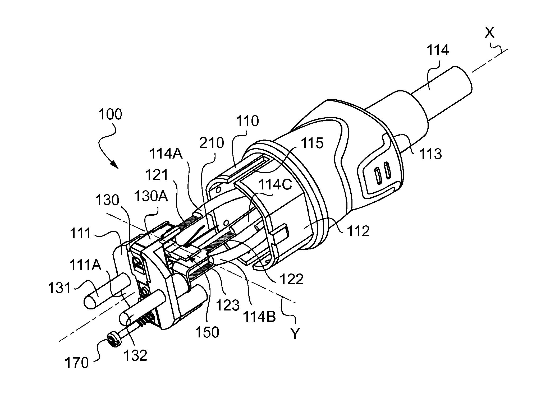
  • Electrical apparatus comprising a temperature sensor housed in a support element
  • Electrical apparatus comprising a temperature sensor housed in a support element
  • Electrical apparatus comprising a temperature sensor housed in a support element

Examples


first embodiment

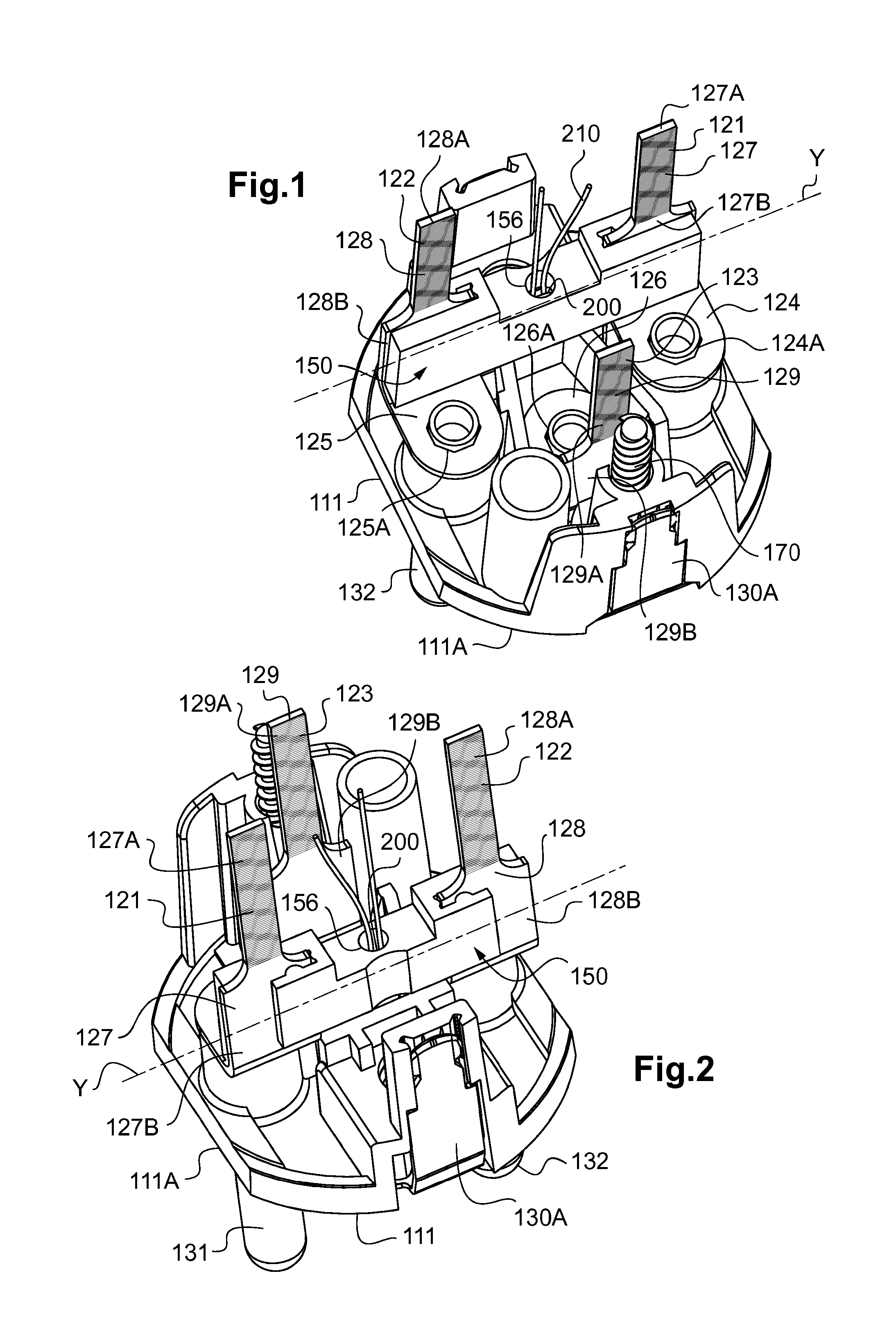
[0031]FIG. 1 is a diagrammatic and fragmentary rear view in perspective of an electrical accessory of the invention, which is of the electrical connection plug type;

[0032]FIG. 2 is a diagrammatic and fragmentary rear view in perspective of the FIG. 1 electrical connection plug, turned through 180 degrees relative to FIG. 1;

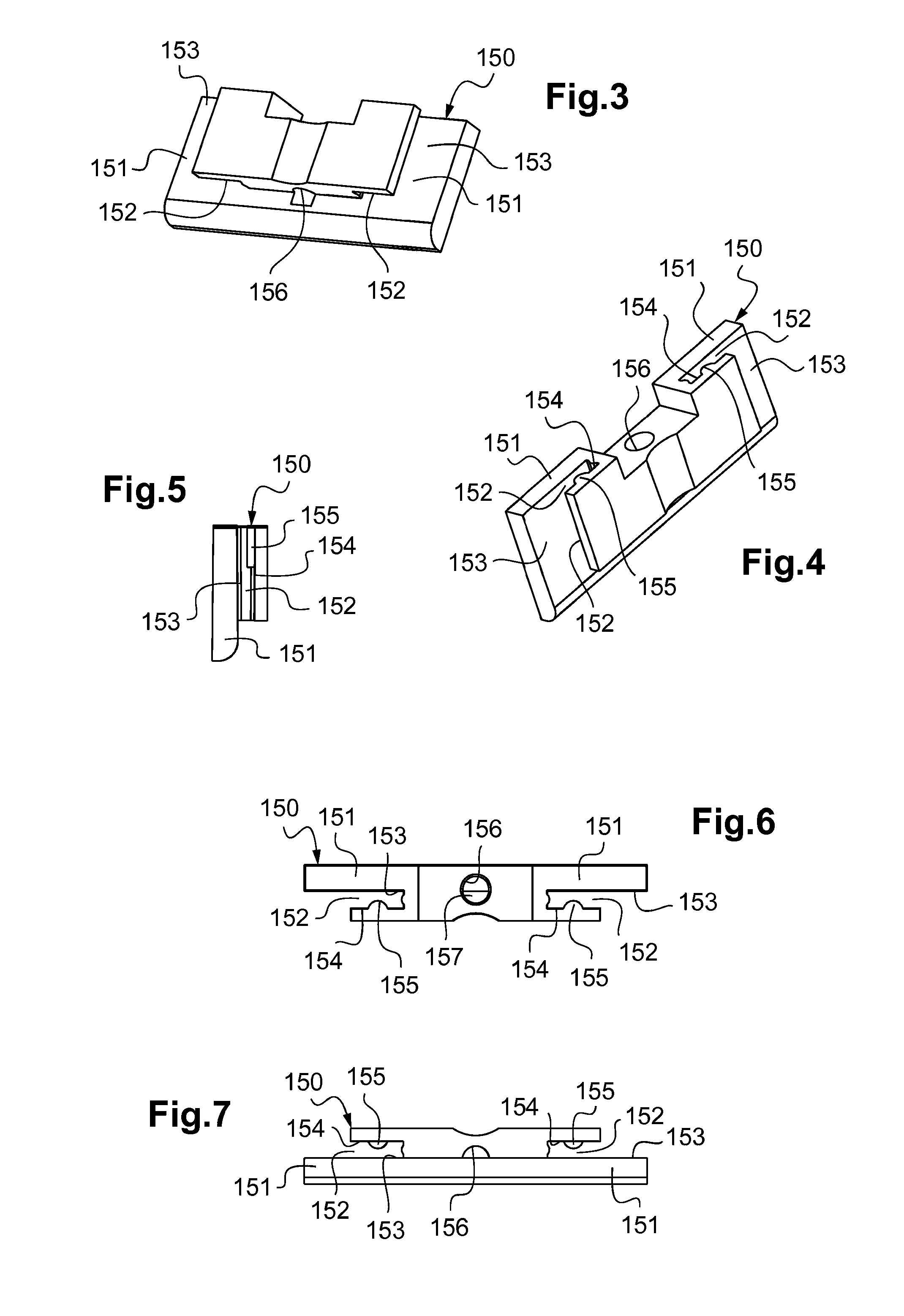
[0033]FIG. 3 is a diagrammatic front view in perspective of the support element of the FIG. 1 electrical connection plug;

[0034]FIG. 4 is a diagrammatic rear view in perspective of the support element of the FIG. 1 electrical connection plug;

[0035]FIG. 5 is a diagrammatic side view of the support element of the FIG. 1 electrical connection plug;

[0036]FIG. 6 is a diagrammatic view of the rear face of the support element of the FIG. 1 electrical connection plug;

[0037]FIG. 7 is a diagrammatic view of the front face of the support element of the FIG. 1 electrical connection plug;

[0038]FIG. 8 is an exploded diagrammatic front view in perspective of the FIG. 1 connection...

second embodiment

[0040]FIG. 10 is a diagrammatic and fragmentary rear view in perspective of an electrical accessory of the electrical connection plug type of the invention;

[0041]FIG. 11 is a diagrammatic and fragmentary rear view in perspective of the FIG. 10 electrical connection plug, turned through 180 degrees relative to FIG. 10;

[0042]FIG. 12 is a diagrammatic view partially in section of the FIG. 10 electrical connection plug;

[0043]FIG. 13 is a diagrammatic rear view in perspective of the support element of the FIG. 10 electrical connection plug;

[0044]FIG. 14 is a diagrammatic view of the rear face of the support element of the FIG. 10 electrical connection plug;

[0045]FIG. 15 is a diagrammatic view of the front face of the support element of the FIG. 10 electrical connection plug;

[0046]FIG. 16 is a diagrammatic side view of the support element of the FIG. 10 electrical connection plug;

[0047]FIG. 17 is an exploded diagrammatic perspective view of the FIG. 10 electrical connection plug;

[0048]FIG...


PUM


Abstract

The invention relates to an electrical apparatus (100) comprising an electrically insulating body (110) housing at least two electrical connection elements (121, 122, 123), and a temperature sensor (200). According to the invention, the temperature sensor is received in a thermally conductive and electrically insulating support element (150) which is separate from said body and mounted inside said body, so as to extend between said electrical connection elements, set back from the outer faces of said body.

Description

TECHNICAL FIELD TO WHICH THE INVENTION RELATES[0001]The present invention relates to an electrical accessory including an electrically insulating body housing at least two electrical connection elements, together with a temperature sensor.[0002]The invention finds a particularly advantageous application in providing a connection plug for an electrical appliance, and a connection plug for recharging a battery of an electric vehicle.TECHNOLOGICAL BACKGROUND[0003]An accessory as described in the introduction is known in particular from Document US 2009 / 0251832, which accessory constitutes an electrical connection plug in which each of the two electrical connection elements is connected to a respective connection pin that projects from the front face of said body.[0004]In order to monitor heating of the electric plug, the electrical accessory described in that document includes two thermistors that are each adhesively-bonded to a respective one of the electrical connection elements of t...

Claims


Application Information

Patent Timeline
IPC IPC(8): H01R13/66G01K1/14G01K13/00G01K7/22H01R24/28H01C7/00
CPCH01R13/6683H01R24/28H01C7/008H01R2105/00G01K7/22G01K1/14G01K13/00H01R2103/00H01R24/30G01K1/16G01K2205/00B60L53/16B60L2240/36Y02T10/70Y02T10/7072Y02T90/14
Inventor CHAUMENY, JEAN-LUCVALADAS, VINCENTNORMAND, ROMAIN
Owner LEGRAND SNC
Learn More