High-viscosity liquid feeding booster pump

a booster pump and high-viscosity technology, applied in the field of booster pumps, can solve the problems of bulky and heavy gear pump, and achieve the effect of reducing unnecessary time and reducing generation

Inactive Publication Date: 2016-04-07
SHINHANG
View PDF3 Cites 1 Cited by
  • Summary
  • Abstract
  • Description
  • Claims
  • Application Information

AI Technical Summary

Benefits of technology

[0020]In accordance with the booster pump of the present invention as constructed above, a problem is solved in that a liquid residue is produced inside the chamber due to the incompleteness of the first-in first-out operation and a sediment solidified or cured over time is separated apart from the inside of the chamber to block the discharge port, so that the charge and discharge of the viscous liquid is performed in a first-in first-out manner inside the chamber and a structure of the pump is improved to prevent the liquid residue from being left in the chamber to minimize generation of solidified or cured substances, thereby reducing unnecessary time and cost and basically preventing an unpredictable accident such as a stop of a production line and thus significantly increasing productivity.

Problems solved by technology

As a metering pump that supplies a high-viscosity liquid quantitatively using a discharge gun, a gear pump is bulky and heavy.

Method used


Image

  • High-viscosity liquid feeding booster pump
  • High-viscosity liquid feeding booster pump
  • High-viscosity liquid feeding booster pump

Examples


Embodiment Construction

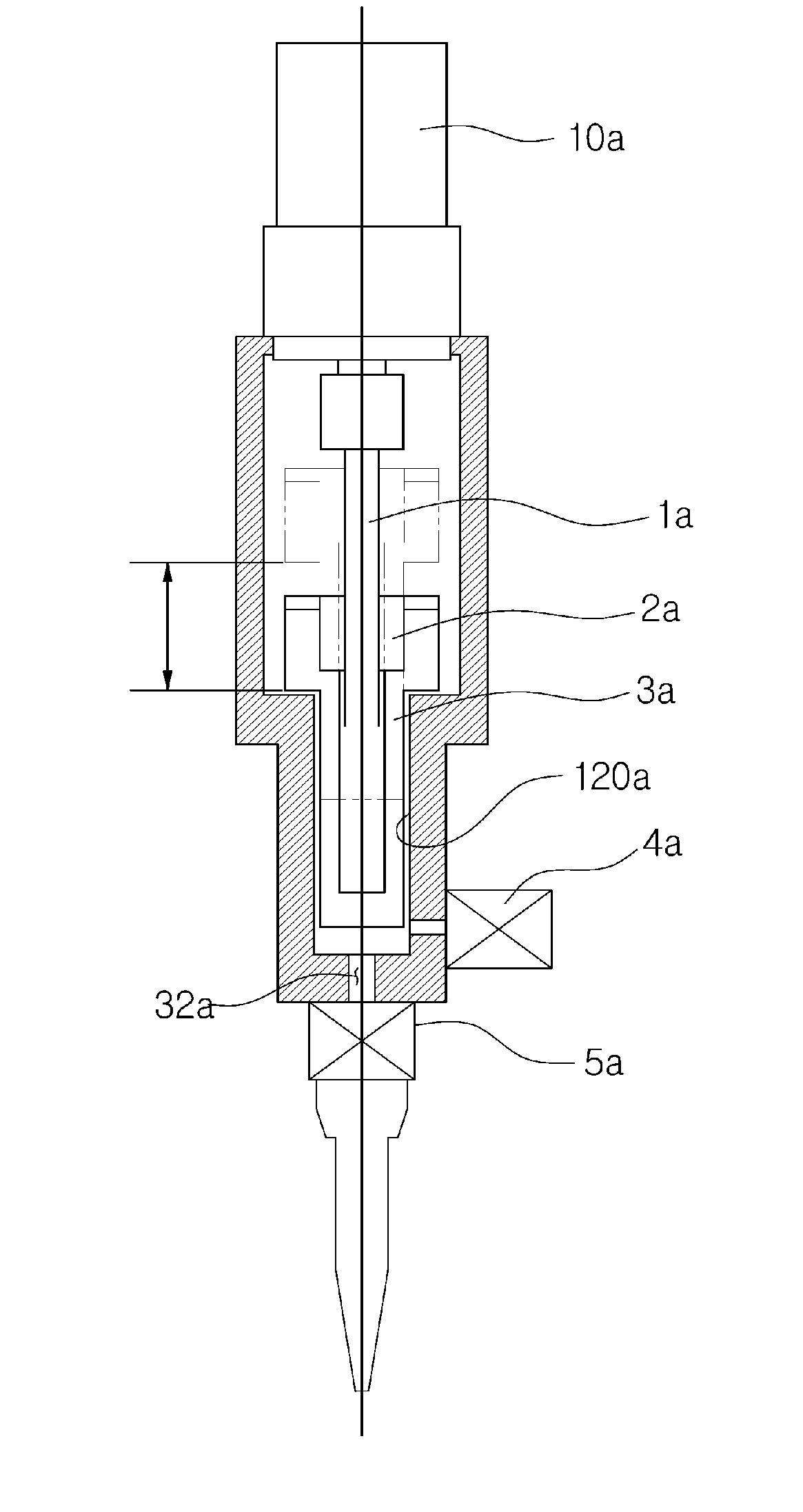
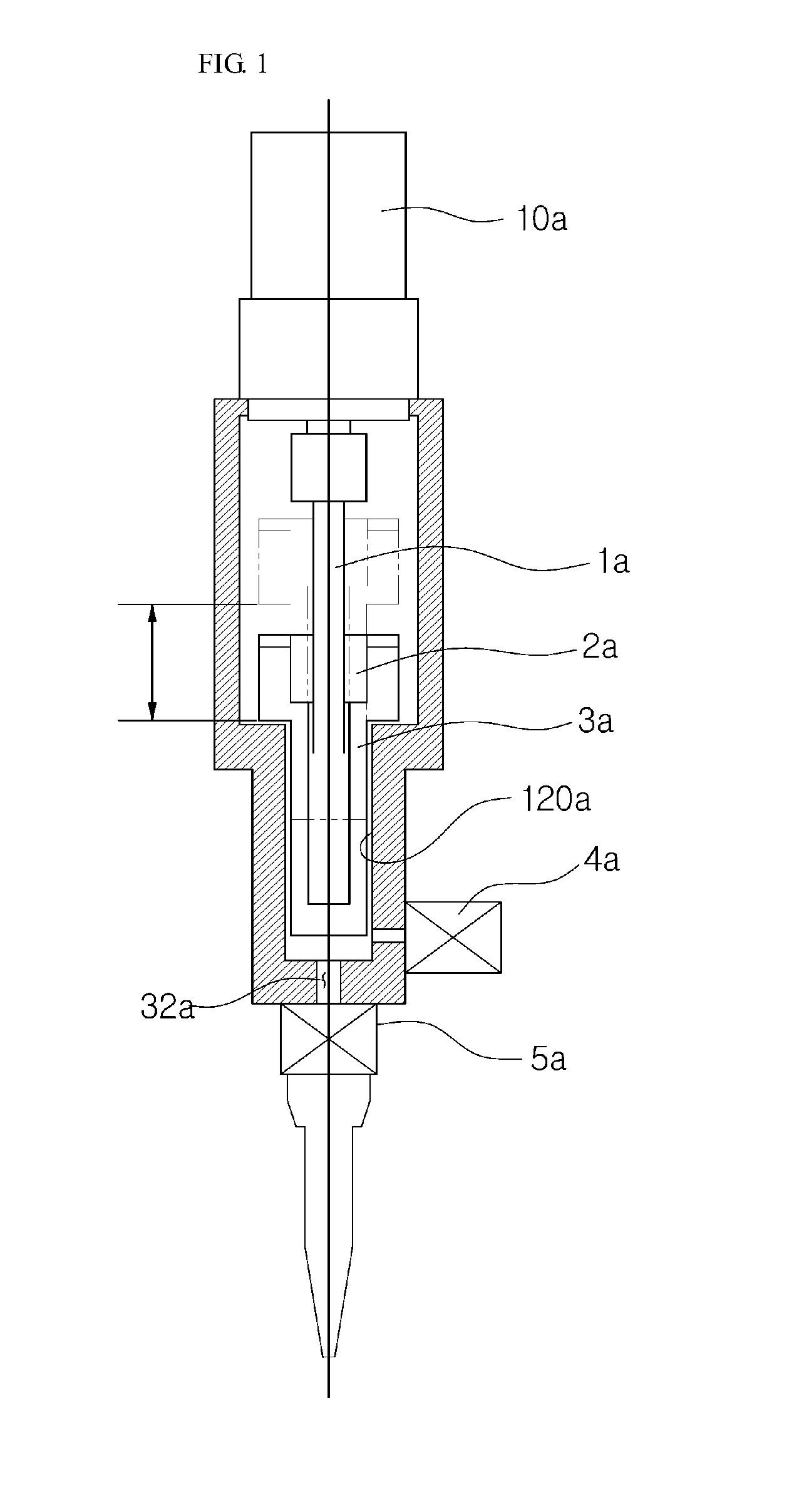
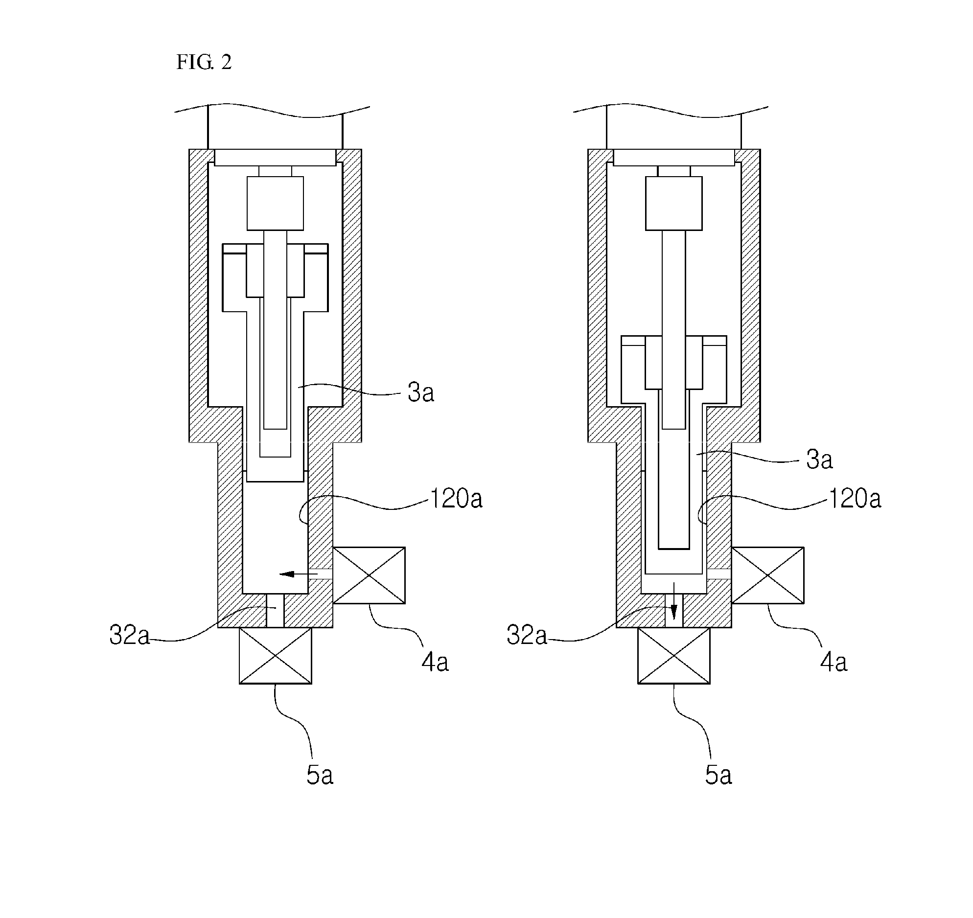
[0036]Hereinafter, the preferred embodiments of the present disclosure will be described in detail with reference to the accompanying drawings. However, the embodiments are for illustrative purposes only and are not intended to limit the scope of the invention. For the sake of a clearer understanding of the present disclosure, the thickness of lines or the size of constituent elements shown in the drawings may be illustrated exaggeratingly for the clarity and convenience of description.

[0037]In the drawings, FIG. 4 is a front cross-sectional view showing a booster pump in accordance with an embodiment of the present disclosure, FIG. 5 is a partially enlarged front cross-sectional view showing the booster pump of FIG. 4, FIG. 6 is a perspective view showing the booster pump of FIG. 5, and FIGS. 7(a) to 7(i) are cross-sectional views showing a liquid filling and discharging process of the booster pump in accordance with an embodiment of the present disclosure.

[0038]As shown in FIGS. 4...


PUM


Abstract

The present disclosure relates to a high-viscosity liquid feeding booster pump. The booster pump includes: a body having an actuator mounted at one side thereof and a discharge valve formed at the other side thereof, the body being formed internally with a chamber; a plunger configured to be inserted into the body, and advanced or retracted relative to the body by the operation of the actuator to generate a compressive force or a suction force; and a charge valve disposed at an intake port formed at an upper portion of one side of the body in such a manner as to be spaced apart from a discharge valve, and configured to be opened or closed in cooperation with the advancing or retracting operation of the plunger to supply a fluid to the inside of the body or interrupt the supply of the fluid.

Description

TECHNICAL FIELD[0001]The present disclosure relates to a booster pump, and more particularly, to a high-viscosity liquid feeding booster pump that minimizes the pulsation of the pump to increase the pressure of the liquid so that the liquid is fed quantitatively.BACKGROUND ART[0002]As a metering pump that supplies a high-viscosity liquid quantitatively using a discharge gun, a gear pump is bulky and heavy. For this reason, a lightweight and pulsation-free secondary metering pump of a piston type based on a ball screw is widely used as a booster pump.[0003]A booster pump is disclosed in Korean Patent Registration No. 10-1250985 (registered on Mar. 29, 2013).[0004]The booster pump of the above patent includes a suction header connected to an intake pipe through which a fluid is supplied to allow the fluid supplied from the intake pipe to be introduced thereto, a discharge header to which a discharge pipe through which the fluid introduced into the suction header is discharged is conne...

Claims


Application Information

Patent Timeline
Patent Type & Authority Applications(United States)
IPC IPC(8): F04B11/00F04B53/16F04B53/10F04B53/14F04B15/02F04B19/22
CPCF04B11/0091F04B15/02F04B53/16F04B53/10F04B53/14F04B19/22F04B15/00F04B53/148F04B53/162
Inventor KIM, HEE KYUNPARK, DONG MAN
Owner SHINHANG
Why Eureka
Try Eureka