
System For Improving Performance Of Wheel Chock Safety Procedures

a technology of safety procedures and loading docks, which is applied in the field of loading docks, can solve the problems of limited space and visibility, the most dangerous location of loading docks in a commercial space, and the need for tractor trailer trucks to maneuver outsid

Active Publication Date: 2016-03-31
DLMFG
View PDF6 Cites 16 Cited by
  • Summary
  • Abstract
  • Description
  • Claims
  • Application Information

AI Technical Summary

Benefits of technology

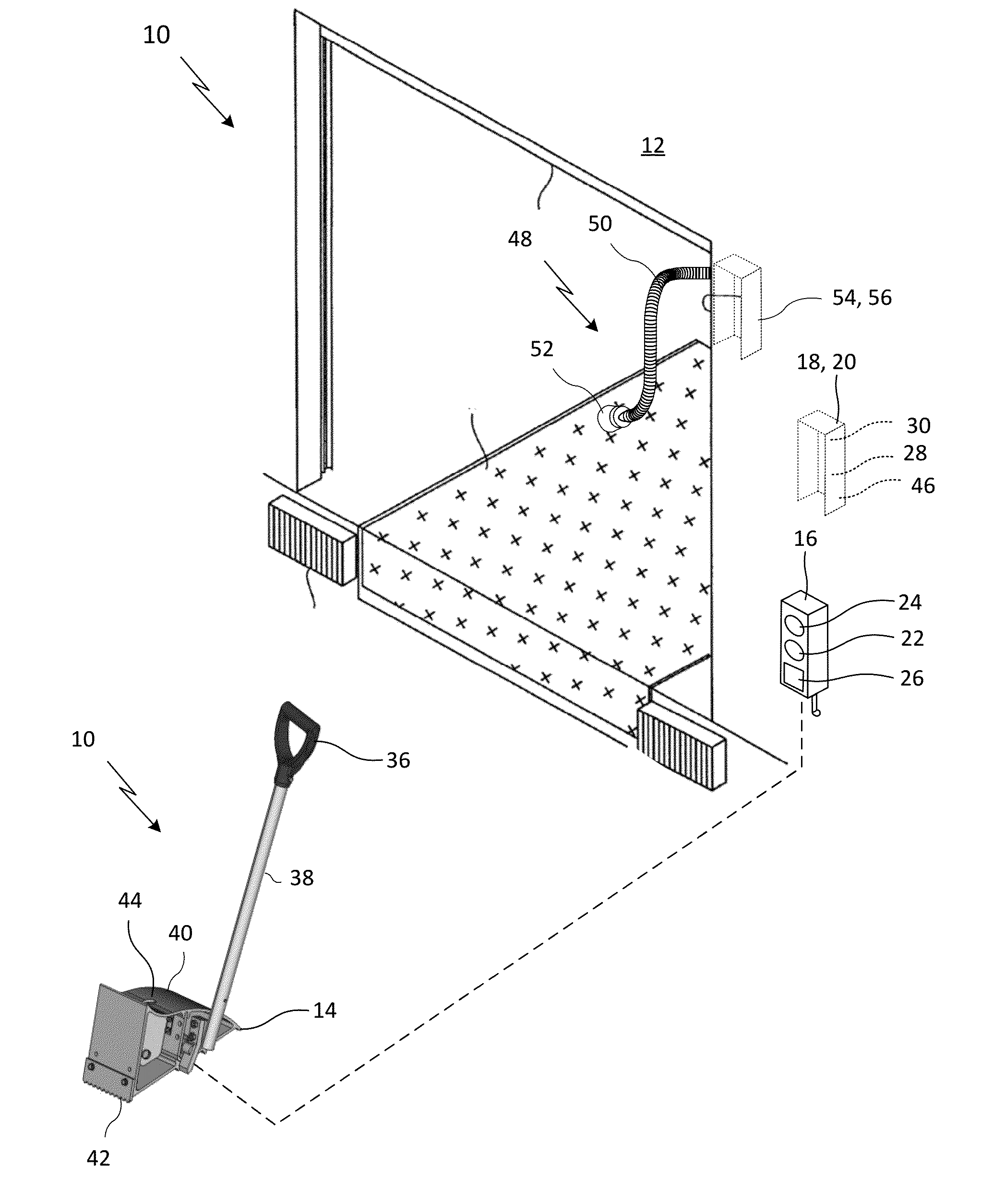
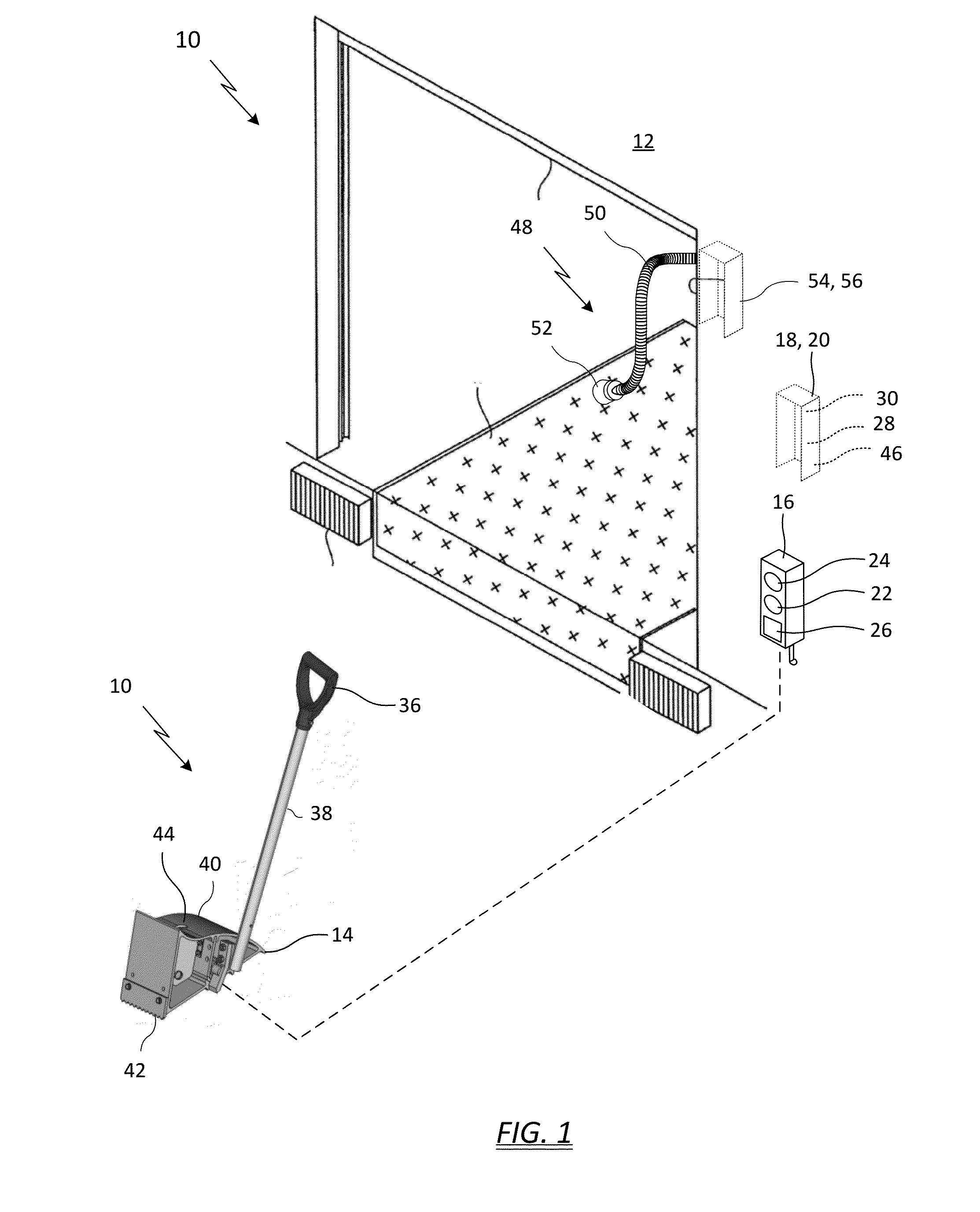
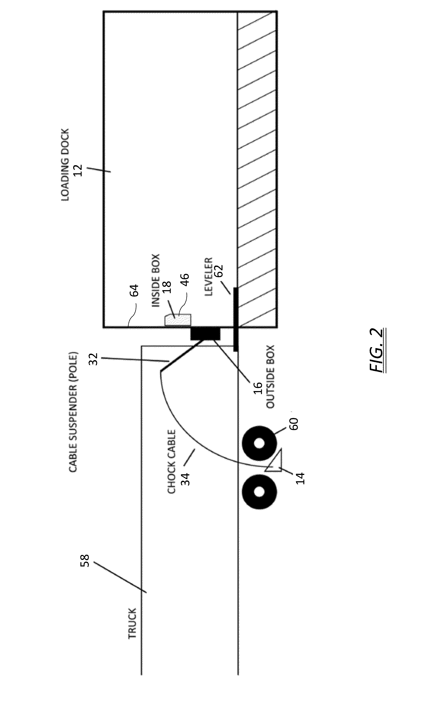
The present invention is for a wheel chock system that can be used to prevent a vehicle (such as a truck or trailer) from moving when it is parked at a loading dock. The system includes a chock assembly with a wheel chock, a shaft, and a handle. The chock is placed against the vehicle's tire to stop it from moving. A sensor in the chock detects when the chuck is close to the tire. The system also has an outside light box that includes one or more lamps to visually indicate the chock is near the tire and to alert drivers of the loading dock's safety status. An inside control panel with lights is also included to provide a visual indication of the safe status of the loading dock. Additionally, the system includes a camera that captures images of the tire and the chock and sends them to a display for safety monitoring. This system ensures the vehicle is secure and safe when parked at the loading dock.

Problems solved by technology

Loading docks are among the most dangerous locations in a commercial space.
Tractor trailer trucks need to maneuver outside the loading dock with limited space and limited visibility.
Inside, fork lift trucks are moving about to and from the loading dock, also with limited space and limited visibility.
One of the worst case accident scenarios at a loading dock can occur when a trailer unexpectedly moves away from the dock.
The forklift operator can be seriously injured, or worse, a portion of the forklift can fall on the driver causing in a fatal crush injury.

Method used


Image

  • System For Improving Performance Of Wheel Chock Safety Procedures
  • System For Improving Performance Of Wheel Chock Safety Procedures
  • System For Improving Performance Of Wheel Chock Safety Procedures

Examples


Embodiment Construction

[0023]Definitions: Wireless module: A wireless module includes any suitable form of wireless communications such as, for example, Wi-Fi, ZigBee, XBee, communication over power lines, or any other suitable form of wireless communications, such as any suitable type of radio frequency (RF) wireless communications. While referred to hereinbelow as a wireless “module”, wireless module is understood to include wireless functionality added by one or more wires, PC posts, or cables literally connected to a wireless module, as well as the equivalent wireless functionality on any suitable circuit board, such as can be provided by one or more discrete components and / or integrated and / or hybrid circuits mounted to one or more circuit boards associated with a controller. The method of construction such as, for example, through hole components, surface mount components, and or more compact technologies such as flip chips and / or other solder bump compatible packages are all understood to fall with...


PUM


Abstract

A wheel chock system includes a chock, a sensor disposed within the chock to sense the proximity to the tire, an outside light box, and an inside control panel. Lamps on the outside light box provide a visual indication as to when the chock is in close proximity to the wheel. Lights on the inside control panel provide a visual indication of the loading dock safety status. The wheel chock system further includes a controller coupled to the inside control panel, programmed to change visual indications of both the outside light signal box and the inside control panel, based at least on the sensor and a loading dock door sensor. The wheel chock system further includes a camera positioned to view the tire and the chock and convey an image of the tire and the chock to a display on or near the inside control panel.

Description

CROSS REFERENCE TO RELATED APPLICATION[0001]Reference is made to and this application claims priority from and the benefit of U.S. Provisional Application Ser. No. 62 / 056,849, filed Sep. 29, 2014, entitled “SYSTEM AND METHOD FOR IMPROVING PERFORMANCE OF WHEEL CHOCK SAFETY PROCEDURES”, which application is incorporated herein in its entirety by reference.BACKGROUND OF THE INVENTION[0002]The application relates to loading docks and particularly to a system and method for improving performance of loading dock wheel chock safety procedures.[0003]Loading docks are among the most dangerous locations in a commercial space. Tractor trailer trucks need to maneuver outside the loading dock with limited space and limited visibility. Inside, fork lift trucks are moving about to and from the loading dock, also with limited space and limited visibility. Pedestrians can also be moving about both outside and inside the loading dock door.[0004]One of the worst case accident scenarios at a loading do...

Claims


Application Information

Patent Timeline
IPC IPC(8): B60T17/22B60T3/00G06T7/00H04N7/18
CPCB60T17/22B60T3/00G06T2207/30252G06T7/0042H04W84/12H04N7/183B65G69/005
Inventor METZ, DONALD, L.EPPLEY, JOSHUA, L.
Owner DLMFG
Learn More