
Wedge holding mechanism for vascular intervention device delivery system

Active Publication Date: 2016-03-17
COOK MEDICAL TECH LLC
View PDF1 Cites 8 Cited by
  • Summary
  • Abstract
  • Description
  • Claims
  • Application Information

AI Technical Summary

Benefits of technology

The vascular intervention device delivery system described in this patent allows for easy and precise placement of intervention devices in blood vessels. The system includes a retractable sheath and a thumbwheel that is rotated in different directions to build up tension in the sheath and pull the catheter without moving it. This allows for smooth operation and maintained positioning of the intervention device during use.

Problems solved by technology

In pin and pull systems, the user can have difficulty maintaining the inner catheter at a fixed position while simultaneously moving the outer sheath.
In very difficult stent deployments, which require a large amount of force by the user, this simultaneous push and pull may lead to inaccurate stent positioning, shortening or lengthening of the stent, or possibly even damage to the stent or target vessel.
Another disadvantage of pin and pull systems is that there can be a lack of control on the deployment because the force to deploy the stent decreases as more of the stent is deployed.
If the user maintains the same high force during deployment, the stent may be deployed too fast for the user to control.
Another potential problem relates to building up tension in the outer sheath prior to movements thereof during the deployment process.
If the user pauses during the deployment and releases this built up tension, deployment errors can occur when the user resumes tension to again move the outer sheath to the deployment position fully uncovering the self explaining stent.

Method used


Image

  • Wedge holding mechanism for vascular intervention device delivery system
  • Wedge holding mechanism for vascular intervention device delivery system
  • Wedge holding mechanism for vascular intervention device delivery system

Examples


Embodiment Construction

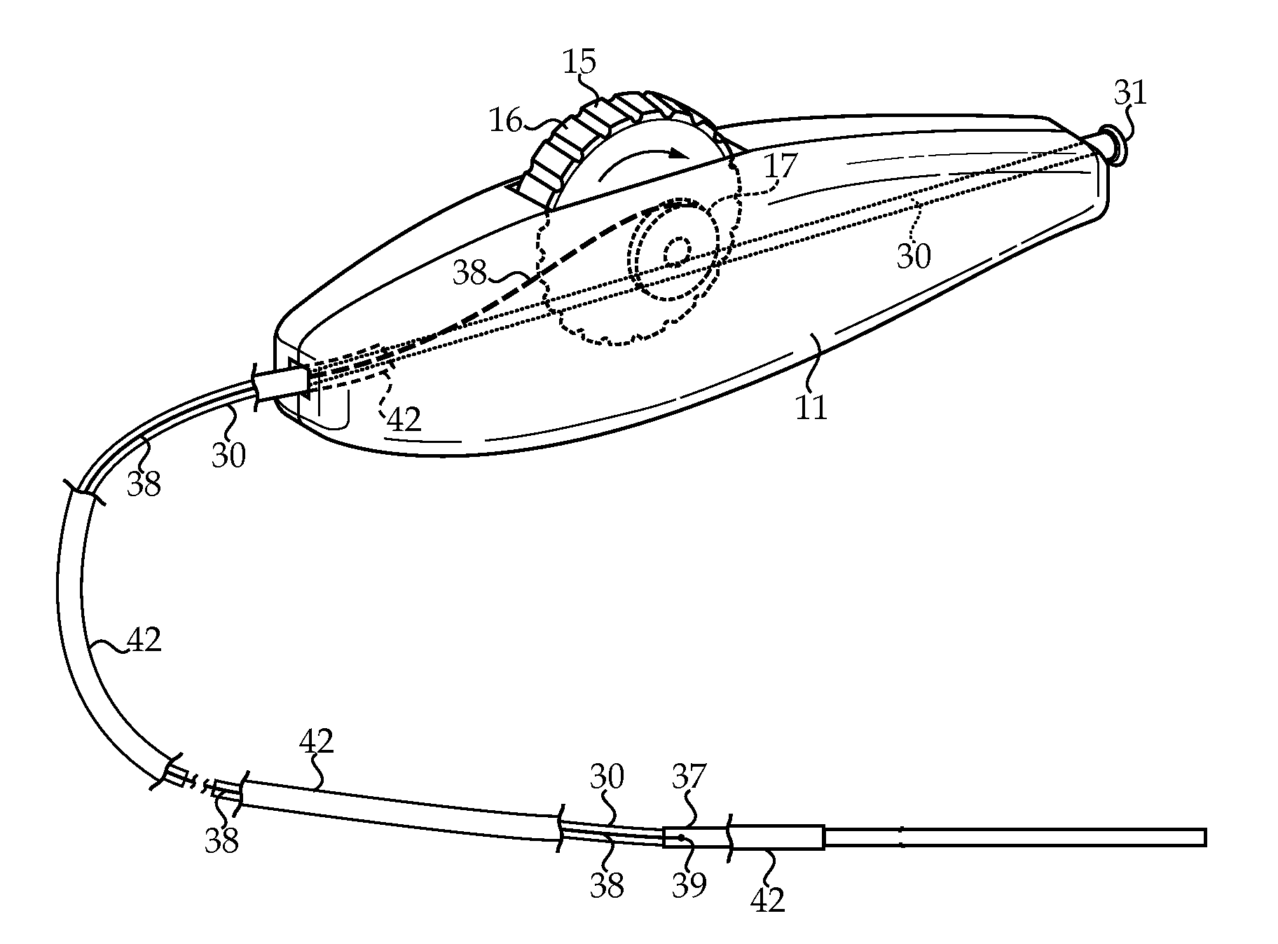
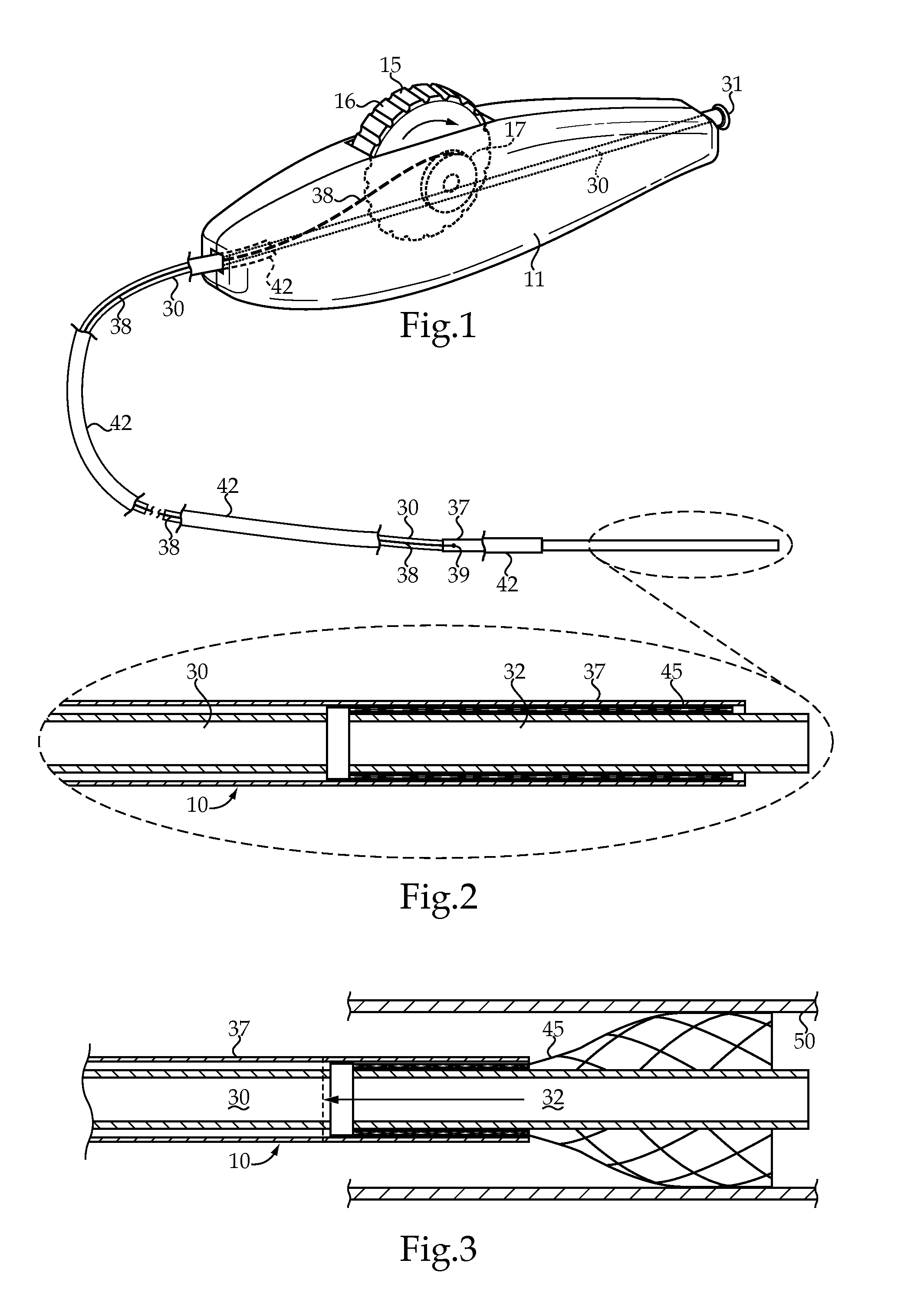
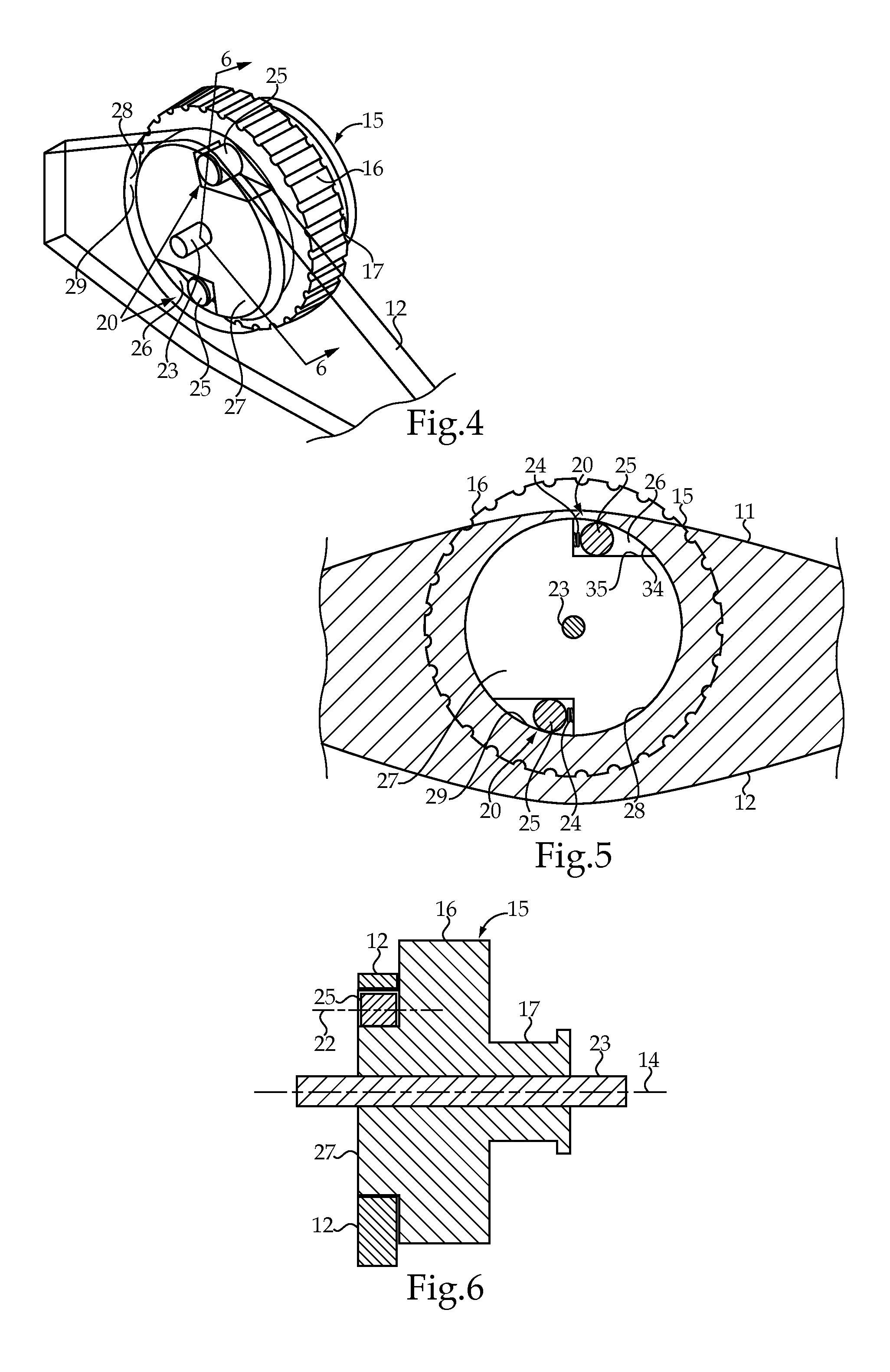
[0015]Referring to FIGS. 1-3, a vascular intervention device delivery system 10 is shown before and during delivery of a self expanding stent 45 into the vessel 50 of a patient. Delivery system 10 includes a handle 11 that may be gripped in one hand by a user during a delivery procedure. Handle 11 may, for instance, be manufactured from a suitable molded plastic, such as in two longitudinal halves that are joined in any suitable manner to form the complete handle 11. A thumbwheel 15 is rotatably mounted on an axle 23 in the handle 11 and has a radially outward thumb surface 15 and a spool 17. A catheter 30 has a proximal end 31 attached to handle 11, and a distal carrier segment 32 for mounting a vascular intervention device, such as a self expanding stent 45, thereon. Proximal end 31 may take the form a Luer lock fitting so that treatment fluids or the like may be injected through catheter 30 in a manner well known in the art. A retractable sheath 37 is movable with respect to cath...


PUM


Abstract

A vascular intervention device delivery system, such as for implanting a self expanding stent, includes a thumbwheel rotatably mounted in a handle. The thumbwheel includes a radially outward thumb surface. A catheter has a proximal end attached to the handle, and a distal carrier segment for mounting a vascular intervention device thereon. A retractable sheath is movable from a first position covering the distal carrier segment to a second position retracted proximally uncovering the distal carrier segment. A pull extends between the thumbwheel and the retractable sheath. A holding mechanism is operably positioned between the handle and the thumbwheel, and includes a wedge pin trapped to move in a wedge shaped cavity between a wedged position that prevents the thumb wheel from rotating, and an unwedged position that permits the thumbwheel to rotate to facilitate deployment of a self-expanding stent.

Description

TECHNICAL FIELD[0001]The present disclosure relates generally to vascular intervention device delivery systems, and more particularly to a feature that holds the thumbwheel against rotation in one direction, but permits rotation in an opposite direction for deployment of a vascular intervention device.BACKGROUND[0002]Self expanding stents and similar vascular intervention devices are often delivered and deployed using so called pin and pull systems. Typically, the stent is compressed between a retractable outer sheath and an inner catheter. To deploy the stent, the user has to pull the outer sheath to uncover the stent using one hand while resisting the force with the other hand on the inner catheter to maintain the position of the stent during deployment. In pin and pull systems, the user can have difficulty maintaining the inner catheter at a fixed position while simultaneously moving the outer sheath. In very difficult stent deployments, which require a large amount of force by t...

Claims


Application Information

Patent Timeline
IPC IPC(8): A61F2/966
CPCA61F2002/9517A61F2/966A61F2/9517
Inventor CUMMINS, SEAN
Owner COOK MEDICAL TECH LLC
Learn More